
by Zubin Dotivala
|
|
Indian Railway Images
by Zubin Dotivala |
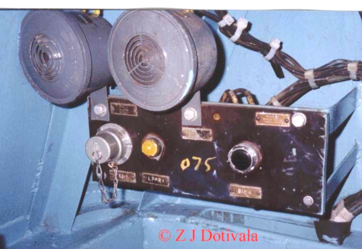 |
Buzzers: These Buzzers buzz when ever there is load parting. The yellow colored indicator (LSPAR) comes on. Right next to this indicator is a 110 Volts outlet socket. At the moment it is covered with a cap that is chained to the socket itself. The green colored switch (BIS) is the resetting switch used to silence the buzzers once things are set right. |
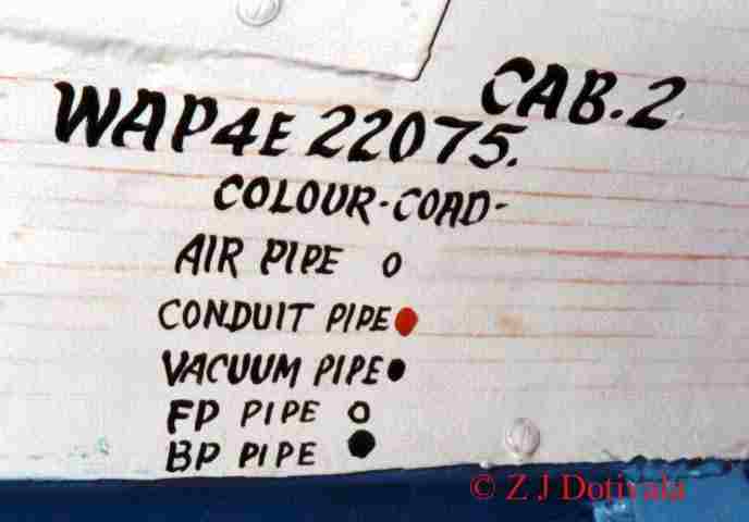 |
That's the color code of the brake pipes, to prevent any interchange or wrong connections. It's painted on the inside wall over the wind shield of the cab. |
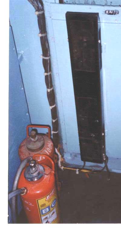 |
Cab heater and Fire extinguisher |
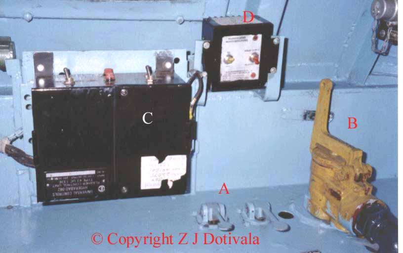 |
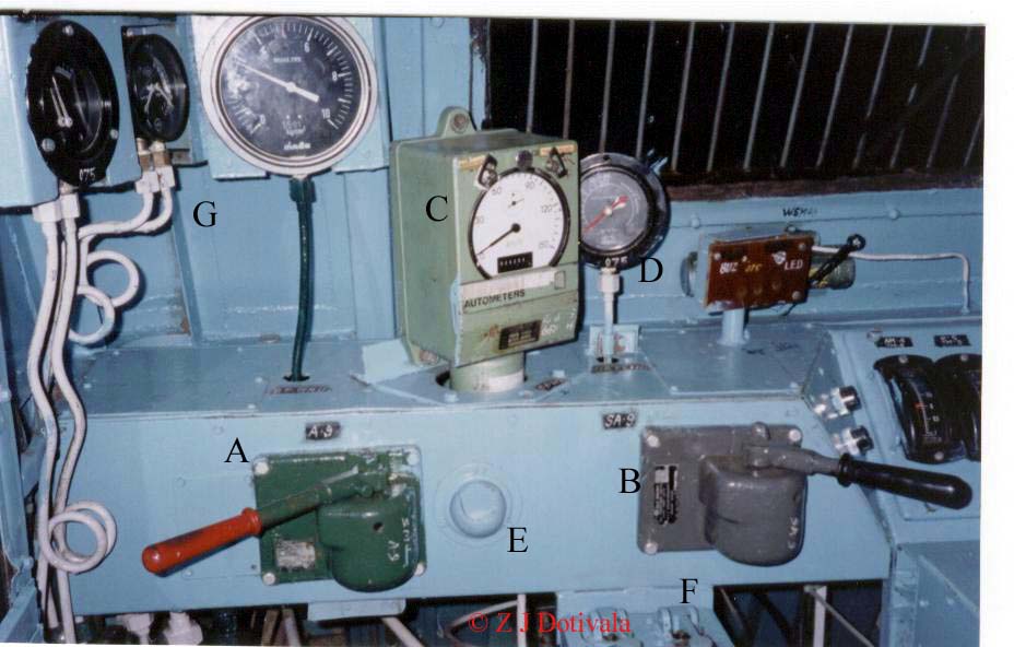
A view of the RHS corner of the loco control desk:
|
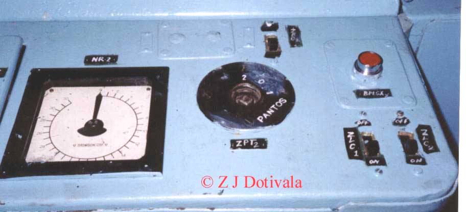 |
A view of the central portion of the control desk:
|
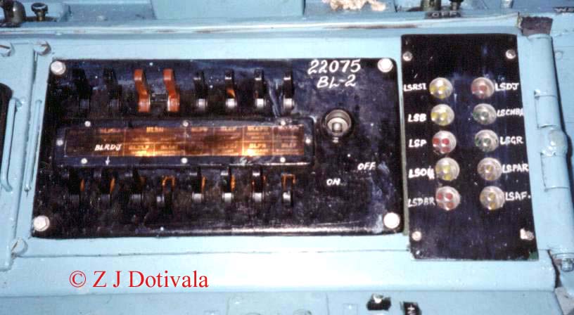 |
The switch board and the indicator lamps module located in the driving cab. |
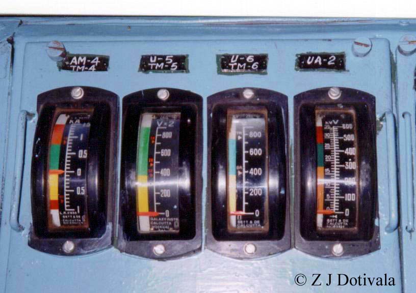 |
Ammeters & Voltmeters:
|
 |
|
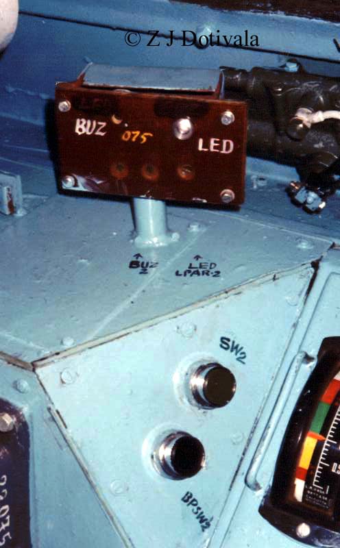 |
These days trains are run at Max speeds. Drivers are instructed to drive in "air brake style" This involves rapid acceleration and equally rapid & frequent breaking. To ensure that the loco can accelerate immediately after brake application, brake release must be immediate. Or time is lost as the driver waits for brakes to release(Impatient drivers have been known to end up with fractured couplers). The Green colored switch shown here, when pressed results in immediate brake release. The Buzzer and LED shown here come on in case of load parting. The other green colored switch is to reset the buzzer after the "All Right" signal is given. |
 |
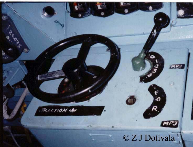
A view of the LHS corner of the cab:
|
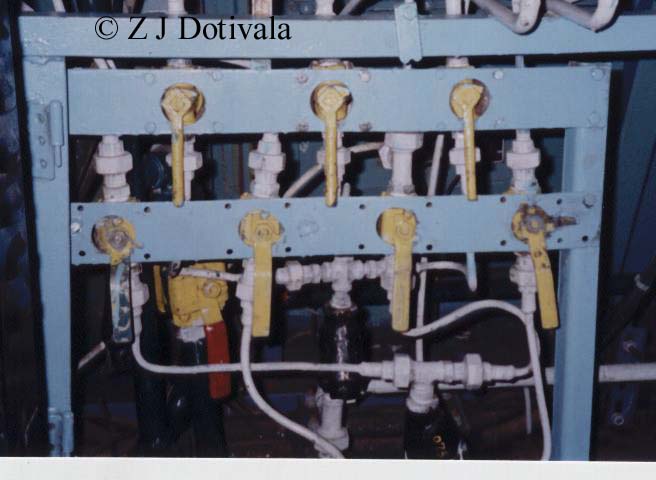 |
Cut out valves: These valves are situated in the lower LHS corner of the loco. One can cut out air to the various pneumatic equipment in the loco. There are two valves for SA9, two valves for SA9 , one for the wiper and two for the horns. |
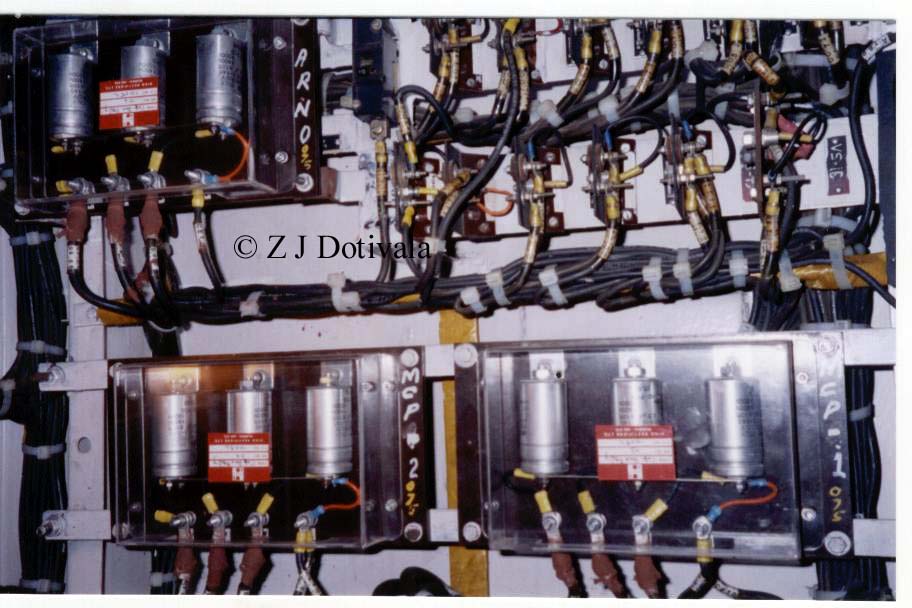 |
These are the capacitors for the Arno and compressor. These are located in a cabinet on the back wall of the cab. |
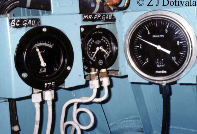 |
A close view of the brake air pressure gauges situated in the extreme LHS corner of the cab. The gauge with the two coiled pipes connected to it shows the main reservoirs pressure and the feed pipe pressure. The larger gauge with graduations from 0 to 10 shows the air pressure in the brake pipe. |
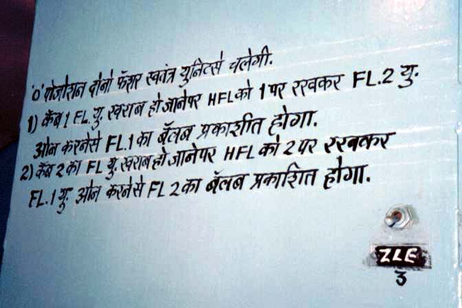 |
ZLE3 is the switch for the light in the compartment on the back wall of the
cab that houses the capacitors for the Arno and compressor. There are two flashers outside the cabs. One on each cab. There are two control units, one in each cab for controlling the flashers. Normally one unit controls one flasher If any one of these flasher units fails than the other unit can control the flashers irrespective of their location. The writing on the wall reads: If the switch is on "0" position both flashers will run individually on independent units. If the flasher unit in cab one malfunctions than the HFL should be put on position "1" Now if the flasher unit in cab two is switched on it will run the flasher located on cab one. If the flasher unit located in cab two malfunctions than HFL should be put on position "2" and flasher unit located in cab one will run the flasher unit located on top of cab two. |
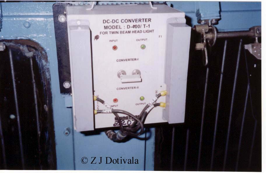 |
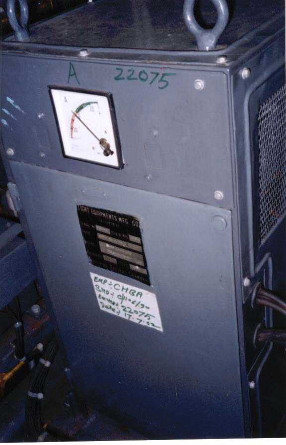
When ever a loco crosses a dead zone the "DJ" has to be opened as a result of this all electrical in the loco including the head light gets switched off. To avoid this a DC-DC Converter is being retrofitted in locomotives. These converters step down the 110 volts from the batteries in the loco to 32 volts which is than supplied to the head light when ever the loco is passing a dead zone. What is shown in this pic is merely the control unit for this converter, there are other transformers which actually do the converting and they can be seen in another pic. |
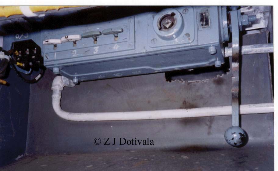 |
This is the VB box. This is a safety device (interlock box) to ensure that OH supply is switched off before a human enters the interior of the loco. The large socket takes in the ZPT key. The keys numbered one to four are the fitchet keys. |
 |
The battery charger. |
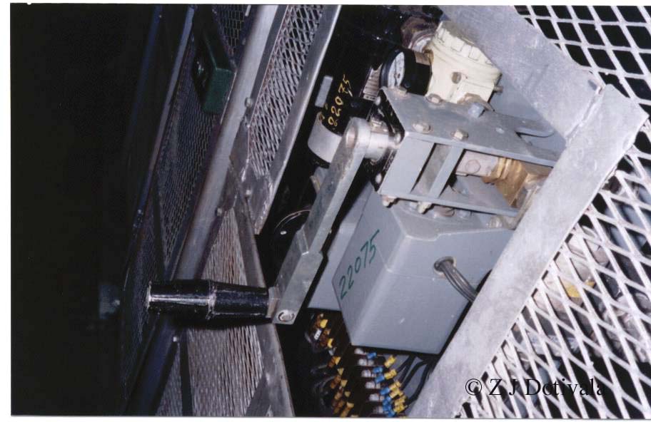 |
This is the GR handle. The notches can be manually increased from here. |
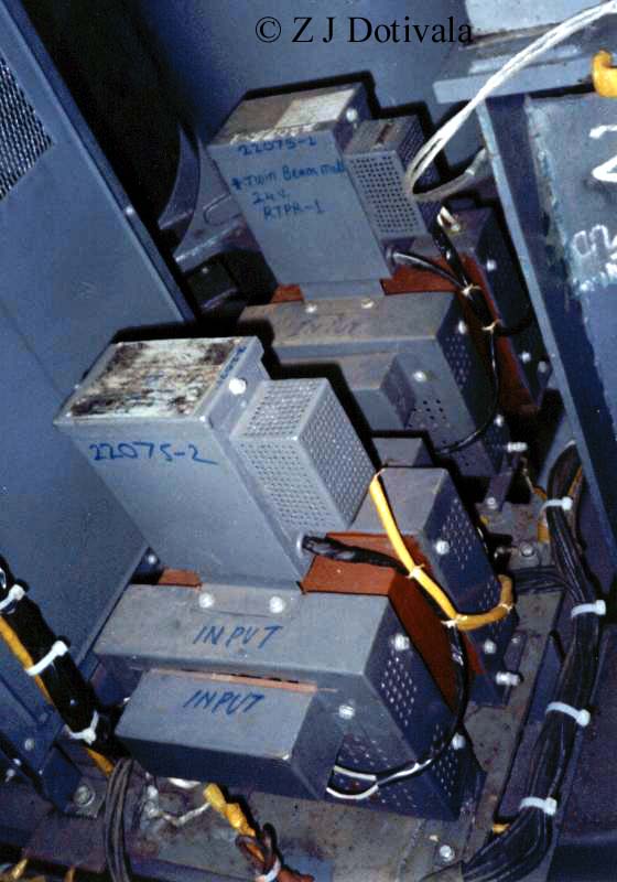 |
The transformer that steps down 110 volts from the batteries to 32 volts. This is supplied to the head lamps when ever the loco crosses a dead zone. |
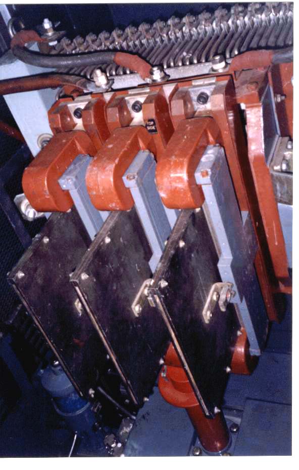 |
This is the contactor for the GR. One can see the thin wire like things behind. These are resistors that come into play when the notches are increased. |
 |
Smoothening reactors: The loco takes in AC from the OHE. This has to be converted to DC before being fed to the traction motors. The main rectifier does this job. But the out put of the rectifier is not pure DC when connected to a CRO it does not give a 100% smooth straight line. To rectify this the smoothening rectifiers are employed. They smoothen the out put of the rectifiers rendering pure DC out put. |
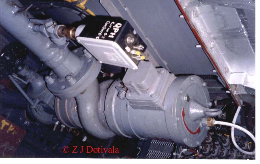 |
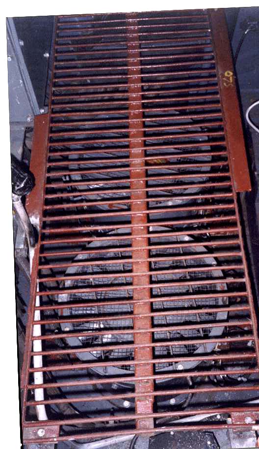
The Pump that circulates the oil in the main transformer to keep temperature under control. |
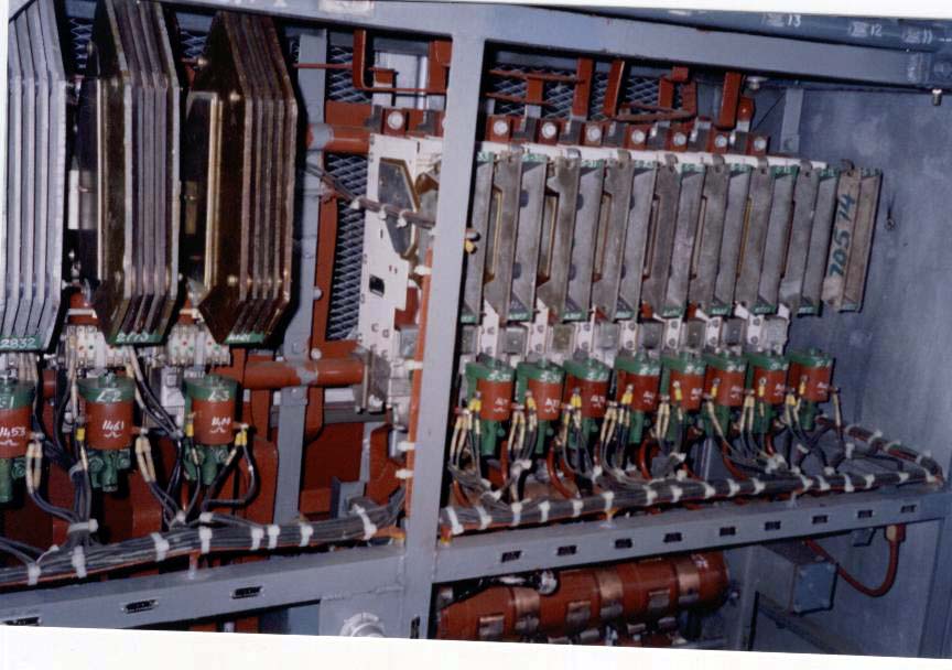 |
Resistance contactors and line contactors. |
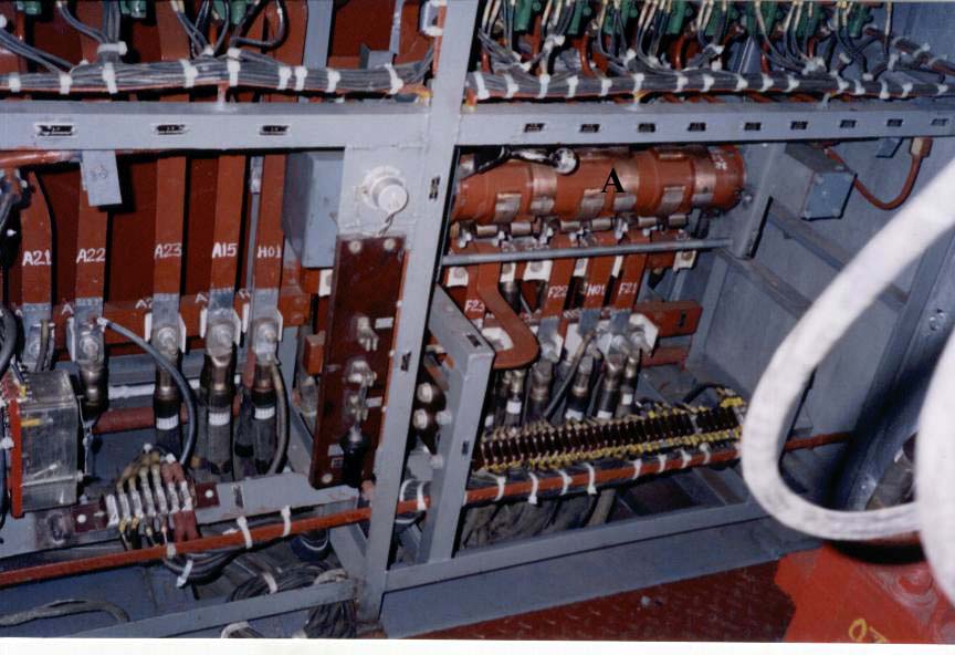 |
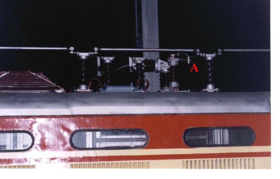
"A": That's the loco reversing contactor. |
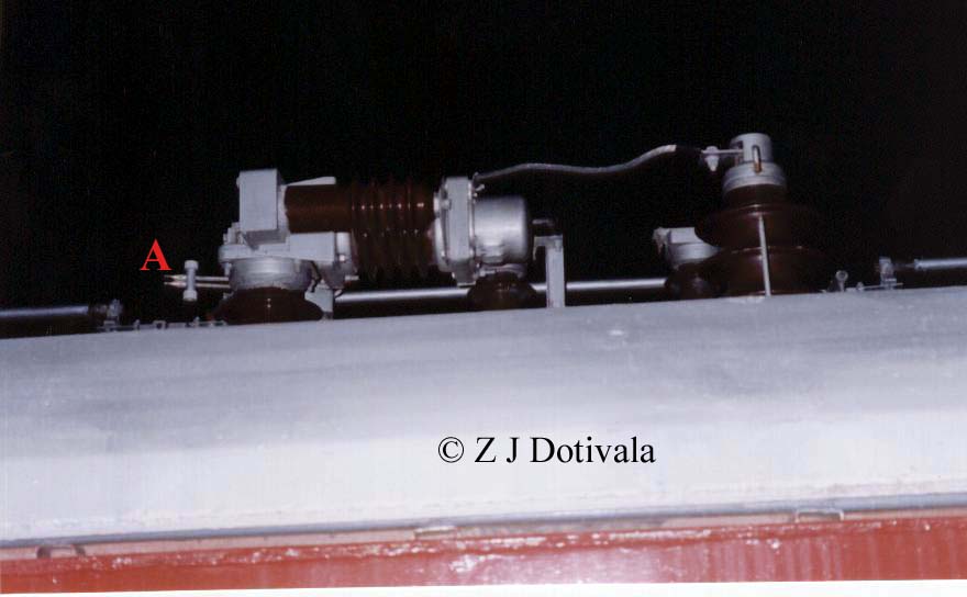 |
"A": That's the DJ main contactor. It's something like a "AB" switch. When in open position it isolates the loco from OHE. The DJ has to be opened whenever the loco crosses a dead zone. |
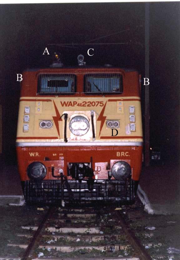 |
Front view of the loco:
|
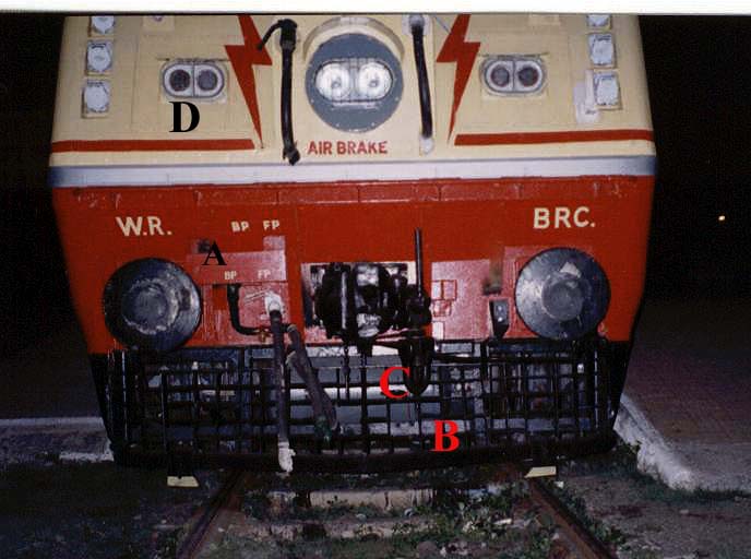 |
Lower front view of the loco:
|
 |
|
 |
A view of the DJ main contactor from the other side. |
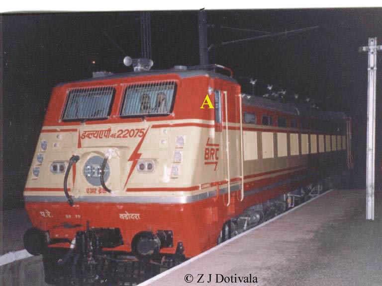 |
A front full view of the Majestic WAP 4 from Vadodara at Badnera. This loco had come to Bhusaval for It's POH. When ever locos under go POH they have a first trial run. They are made to haul lightly loaded passenger train. A WAM 4 is right behind this loco just waiting to take over in case the newly overhauled loco acts up. "A": This is the green colored signaling lamp. This is used to exchange signals with ground crew when the loco runs at high speeds. |