Electric Traction - II
On this pageFor information on history of electric traction in India, 3-phase locomotives etc., please refer to this page.
Electric Traction Systems
Q. How does electric traction work?
In OHE, or overhead electrification systems, the supply of electricity is through an overhead system of suspended cables known as the catenary. A contact wire or contact cable actually carries the electricity; it is suspended from or attached to other cables above it which ensure that the contact cable is at a uniform height and in the right position. In the following the term catenary is loosely used even when talking about the contact wire.
The loco uses a pantograph, a metal structure which can be raised or lowered, to make contact with the overhead contact cable and draw electricity from it to power its motors. (Usually it goes first through a transformer and not directly to the motors.) The pantograph has one or two blades, shoes or collector pans that actually slide against the contact wire. The DC pantographs generally had two shoes, while the AC pantographs have one shoe, owing to the higher current carried by the DC pantograph. The WCAM series of dual-voltage locos had one DC pantograph and one AC pantograph each, but either could be used as a backup for the other traction supply if needed. WCAM locos now sport only AC pantographs. The AC-DC EMUs in the Mumbai region use a single arm pantograph with twin blades.
The pantograph structure may be in the form of a single arm - a single open bent angle ('>'). The diamond form (rhombus) ('<>') was more common for the DC locos. The single arm types are generally oriented with the bend of the pantograph pointing forwards (in the direction of motion, “knee leading”) although this is not a strict rule and locos exist with pantographs in both orientations. Compressed air is used to raise the pantograph from its resting position to the raised position where its shoes touch the contact wire.
The return path for the electricity (the return current) is through the body of the loco and the wheels to the tracks, which are electrically grounded. Ground connections are provided from the rails at periodic intervals. Since the body of the locomotive and the wheels are all metal (steel in most cases) they are quite conductive. Axle brushes are used to electrically connect the rotating axles to the body of the locomotive. Between the wheels and the rails, usually the return current flows well, but conductivity may be reduced in cases of dirt and debris on the rails, or if embedded particles of soot, coal dust, or films of oil, etc. form an insulating layer on the top of the rails. The voltages and currents involved are such that such thin insulating films are easily punctured and a conductive path established at the rail-wheel contact point. After flowing from the wheels to the rails, the return current flows through the rails and also partly through the earth beneath and along it. Bonding cables or bonding strips are provided at rail joints (connecting the rails on either side of a fishplated joint) to ensure continuity of return current flow in the rails (in case the joint is not conductive because of dirt, rust, and so on, and also to allow permanent way operations that involve loosening the fishplates). Earthing cables and earth bond conductors are provided periodically to keep the rails firmly connected to earth and at earth potential and therefore prevent them from developing a floating potential or step voltage that may be hazardous.
Modern electric locos have some fairly sophisticated electronic circuitry to control the motors depending on the speed, load, etc., often after first converting the incoming 25kV AC supply to an internal AC supply with more precisely controlled frequency and phase characteristics, to drive AC motors. Some AC locos (WAG-5, WAM-4) have DC motors, instead. Some AC locos (WAP-5 and WAG-9, both designs from ABB) generate 3-phase AC internally using a thyristor converter system; this 3-phase supply is then used to power asynchronous AC motors. (3-phase AC motors are somewhat more efficient, and can generate higher starting torque.)
The high-voltage systems of adjacent cars are not connected together in the AC-DC EMUs, so a rake of these can go through a transition in the OHE power supply (where one car is on the AC section, another may be in a neutral section, and a third is in the DC section, for instance) without having to coordinate raising or lowering pantographs among all of them.
In 3rd-rail systems, electricity is supplied through a thick conductor (the third rail) running along the track; the loco has a shoe which maintains sliding contact with it while the train is in motion, to draw current from it. Third-rail traction is seen only in a few metro systems in India. 3rd-rail systems are usually DC systems at much lower voltages (500V-750V or so).
DC System
In DC systems with overhead catenary, the basic principle is the same, with the catenary being supplied electricity at 1.5kV DC. Usually (especially for EMUs) the current from the catenary goes directly to the motors. A DC loco may however convert the DC supply to AC internally using inverters or a motor-generator combination which then drives AC motors.
The generally lower supply voltages of DC systems implies that the currents drawn from the OHE are correspondingly higher. This results in some difficulties, among them the need to use thicker and heavier contact wires and pantographs and to keep the pantograph pressed more firmly against the contact wire causing more wear and tear.
Single System (AC)
The overhead catenary is fed electricity at 25kV AC (single-phase) from feeding posts which are positioned at frequent intervals alongside the track. The feeding posts themselves are supplied single-phase power from substations placed 35-60km apart along the route. The substations are spaced closer (down to 10-20km) in areas where there is high load / high traffic. (These substations in turn are fed electricity at 132kV AC or so from the regional grids operated by state electricity authorities.) A Remote Control Centre, usually close to the divisional traffic control office, has facilities for controlling the power supply to different sections of the catenaries fed by several substations in the area.
There are a couple of variations of the AC system, as described below.
Booster Transformer (BT) System
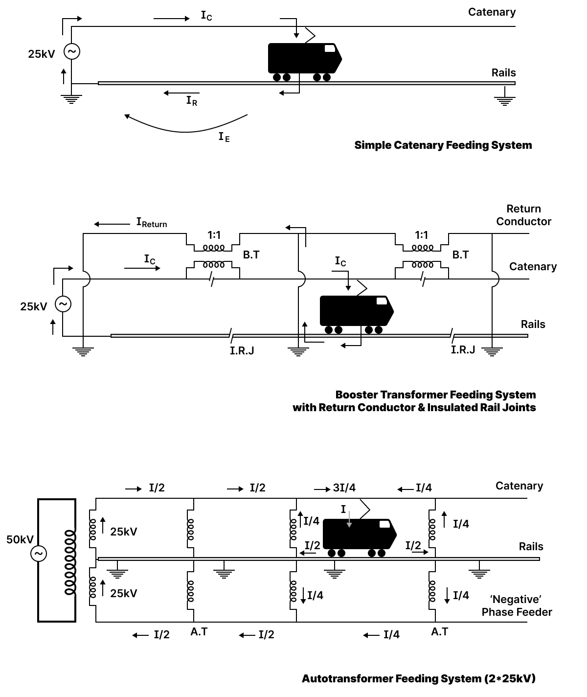
In the simple AC system described above, there can be severe inductive interference in telecom lines and other equipment because of the large loop area between the catenary and the rails which carry the return current (IR in the top diagram in the schematics). Some of the return current also flows in the earth (shown as IE in the top diagram), causing conductive interference and corrosion problems in buried cables, pipes, etc. Such earth currents are higher if the conductive path in the rails is degraded because of rail joint problems.
The middle diagram is a schematic for the booster transformer (BT) feeding system. There is now a return conductor, a wire that is close to and parallel to the catenary wire. The return conductor is connected to the rails (and earthed) as shown. Periodically, there are breaks in the catenary where the supply current is forced to flow through one winding of a booster transformer (marked B.T.); the other winding is in series with the return conductor. The 1:1 turns ratio of the BT means that the current in the catenary (IC) will be very nearly the same as the current in the return conductor (Irw). The current that flows through the loco goes to the rails but then up through a connecting wire to the return conductor, and through it back to the substation.
Insulated rail joints (marked I.R.J.) are also provided — this ensures that current flows in the rails only in the particular section where the loco is present. At all other places, the inductive interference from the catenary current is nearly cancelled by that from the return current, thus minimizing the interference effects. The problem of stray earth currents is also reduced.
One of the disadvantages in this system is that as a loco passes a booster transformer, there is a momentary interruption in the supply (because of the break in the catenary) with the attendant problems of arcing and transients on the line, as well as radio frequency interference.
In recent years, as much telecommunication cabling has been moved away from railway lines or re-laid underground, interference from the electric traction system is not as much of a problem as it used to be in the past, and therefore in many cases the booster transformers and return conductors have been removed and the traction system has been reverted to the plain single-wire system.
A simpler variant of the booster transformer system, where there is no return conductor, but instead the booster transformer's secondary is connected to the rails, has also been used. This is cheaper to install, but suffers from several flaws and does not thoroughly reduce return currents flowing in the earth outside the rails.
Autotransformer (AT) System / 2x25kV System / ‘Dual’ System
Both the simple AC feeding scheme and the booster transformer scheme suffer from voltage drops along the length of the catenary — locos may see severely reduced voltages (by 5kV or more) at points far from the substation. The last diagram is a schematic for an autotransformer (AT) feeding system, which is intended to address this voltage drop problem. The current flow is more complex here. A 50kV supply from the substation is split with a three-winding transformer into a dual 25kV supply (also sometimes called a '2-phase' supply). Between the catenary and the rails is 25kV of voltage. Between the rails and the other phase is also 25kV of voltage (but always instantaneously opposed in sense - 180 degrees out of phase). This other phase (sometimes called 'negative' phase which is a bit misleading since there's no positive or negative here, it's AC) is carried on a feeder wire parallel to the catenary.
There are autotransformers (marked A.T.) provided periodically as shown. These are usually tap-changing transformers that can adjust their turns ratio as required — the aim is to keep the voltage drop between the rails and the catenary always at 25kV as far as possible. But neglecting voltage drops, the turns ratio of these autotransformers is essentially 1:1 between catenary and rails and rails and feeder.
Consider the loco as shown, drawing a load current I. Each phase (catenary and feeder) carries half of this. The currents split and merge as shown in the section just where the loco is. The autotransformer action forces equal currents to flow between the rails and the catenary and between the rails and the feeder in all cases. Note that the rails carry less than the full load current in each direction away from the loco, and that's the only section where the rails carry current. (The rails are shown carrying equal currents I/2 in each direction away from the loco, but that's a simplification - they do not have to be symmetric in that way as long as the two currents add up to load current drawn by the loco.) Note further that the full load current does not flow in the catenary anywhere either. Also, in all the other sections except where the loco is, the catenary and feeder carry equal but opposite currents, providing for the cancellation of inductive interference as in the BT system. The net effect is that in the unoccupied sections the inductive interference is as low as with the BT system, and in the occupied section it is lower than in the BT system. At the same time, the voltage drop problem is eliminated.
Further, there are no unnecessary breaks in the catenary, reducing radio frequency interference and transients on the power system. The reduced currents and 50kV supply also mean that substations can also be farther apart. Thus far the 2*25kV system is in use in only about 10% of all of IR's electrified routes. The important coal-hauling route Bina - Katni - Anuppur - Bishrampur/Chirimiri of WCR/SECR was the first to get this system. The project was set up with assistance fom Japanese Railways Technical Services (JARTS), who also helped set up the Anuppur traction substation. The Dedicated Freight Corridors (DFCs) also use the 2*25kV system. (2001) Badnera - Bhusawal is another section that had this system, but was converted back to the simpler standard feeding system. A couple of other small sections that had the 2x25kV in the past have also now been reverted back to the simpler standard system.
The dual system corresponds to what is called the 3-wire system (with transmission line) in other railways
Substations
As stated above, the substation is where the electricity from the supplying regional grid (at 440kV, 220kV, 132kV, or 110kV) is transformed to a voltage suitable for use for the railways, and fed to the various sections of the catenaries. An AC substation is generally fed 3-phase power, and the phases are split out so that a given catenary section gets only one phase supplied to it. Both AC and DC systems have transformer sections to convert the voltage to a suitable level, and also capacitor banks (sometimes along with thyristor switching circuits) to improve the power factor. The transformers are of 20 - 30 MVA capacity. DC substations in addition also had rectifying units to convert the AC to DC. The Traction Power Controller (TPC) is the official who has the job of monitoring the part of the system served by the substation and can switch the supply to the OHE on or off, change configurations of transformer taps (after shutting down the system), control the capacitor banks to adjust power factor and voltage (older substations only — nowadays this is done automatically), etc.
Feeding Posts
The 25kV AC power from the substation is normally led by two feeder cables or feeders to a feeding post. Each feeder has two conductors, one insulated for 25kV for connection to the busbar, and the other insulted for a lower voltage (3kV) for connection to the track for the return current. The feeders are connected to two sets of busbars with bus couplers, so that either feeder can be used to supply the OHE if one of them is out of action because of a fault or for maintenance. Normally both feeders supply the OHE. Each feeder also has a circuit breaker that can be controlled remotely.
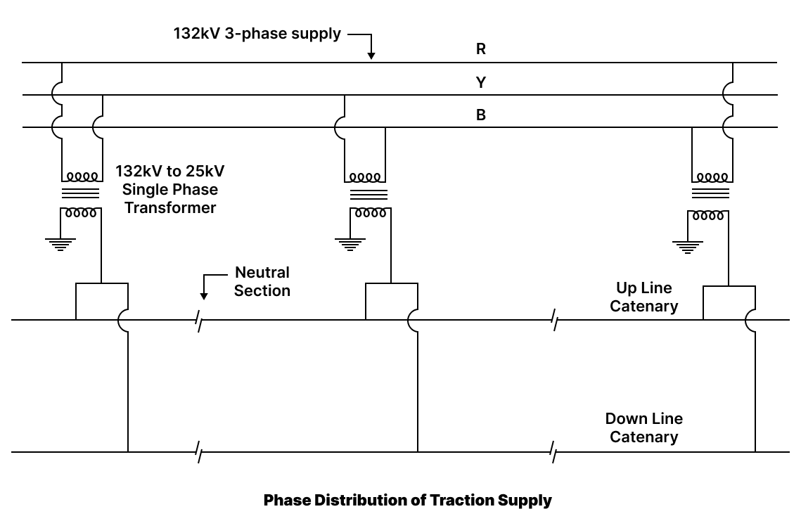
Phase Distribution
To balance the power drawn on different phases of the 3-phase 132kV grid supply, typically different sections of track are provided with power from different phases. It is often set up so that adjacent substations are supplied by different phases. Consecutive AC substations, therefore, are electrically not connected in parallel; this is very different from DC traction systems where all substations are always in parallel.
Sectioning and Paralleling
The portion of the OHE between a feeding post and the next neutral zone on one side is called a section of the traction supply. A substation normally supplies power to two sections, these sections consisting of the up and down OHE portions between the feeding post and the neutral section on either side. A sectioning and paralleling post (SP) (or sometimes sectioning post) is provided near the neutral zone, that has two paralleling interruptors to keep the two portions of the OHE (one in each direction) supplied in parallel. Bridging interruptors are with undervoltage relays are provided to allow feeding of a section that is normally supplied by an adjacent feeding post, in an emergency. When this is done, the portion of the catenary near the next feeding post has to be treated as a phase gap as there could be different phases supplying the sections on either side, and drivers have to lower their locos' pantographs when crossing that feeding post. Note that on IR neutral sections are not provided immediately at the feeding post as is done in some countries, but only at the sectioning posts. This is because bridging adjacent sections is done only as a manual measure in case of an emergency and the risk of short-circuiting adjacent sections supplied by different phases is considered to be low.
A section may be divided into subsections by the provision of subsectioning and paralleling posts (SSP) every 10-15km. Each such SSP has a two bridging interruptors for bridging adjacent subsections, and a paralleling interruptor to parallel the up and down tracks. A subsectioning post is a variant where no paralleling interruptor is provided (rare).
An elementary section is a smaller subdivision of a subsection, which can be rapidly isolated for the purposes of maintenance and repairs. Adjacent elementary sections are connected by insulated overlaps and bridged by isolators that are manually operated when needed (so-called gang switches may be provided to operate the isolators.
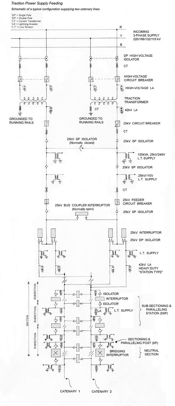
Below is shown a schematic diagram of a typical traction power supply feeding system for an example of how the power supply from the regional grid is converted to the 25kV supply for the catenary.
Substations are generally closer together on DC systems than AC systems, because the latter allow the use of higher voltages and lower currents drawn, so that voltage drops because of the locos on the section are lower.
Transmission Voltage
Power is transmitted to the electrical substations at 750kV, 220kV, 132kV, or 110kV and then stepped down as required to 25kV or 50kV. The power from the grid is usually in the form of 3-phase power.
Catenary Voltage
In practice, the catenary voltage in the 25kV AC system can vary from something like 18kV to over 30kV because of poor regulation at the substation or incorrect configurations of the transformers, etc. Most locos are designed to handle a certain range of catenary voltages, although of course the operation may be less than optimal at voltages far from the norm.
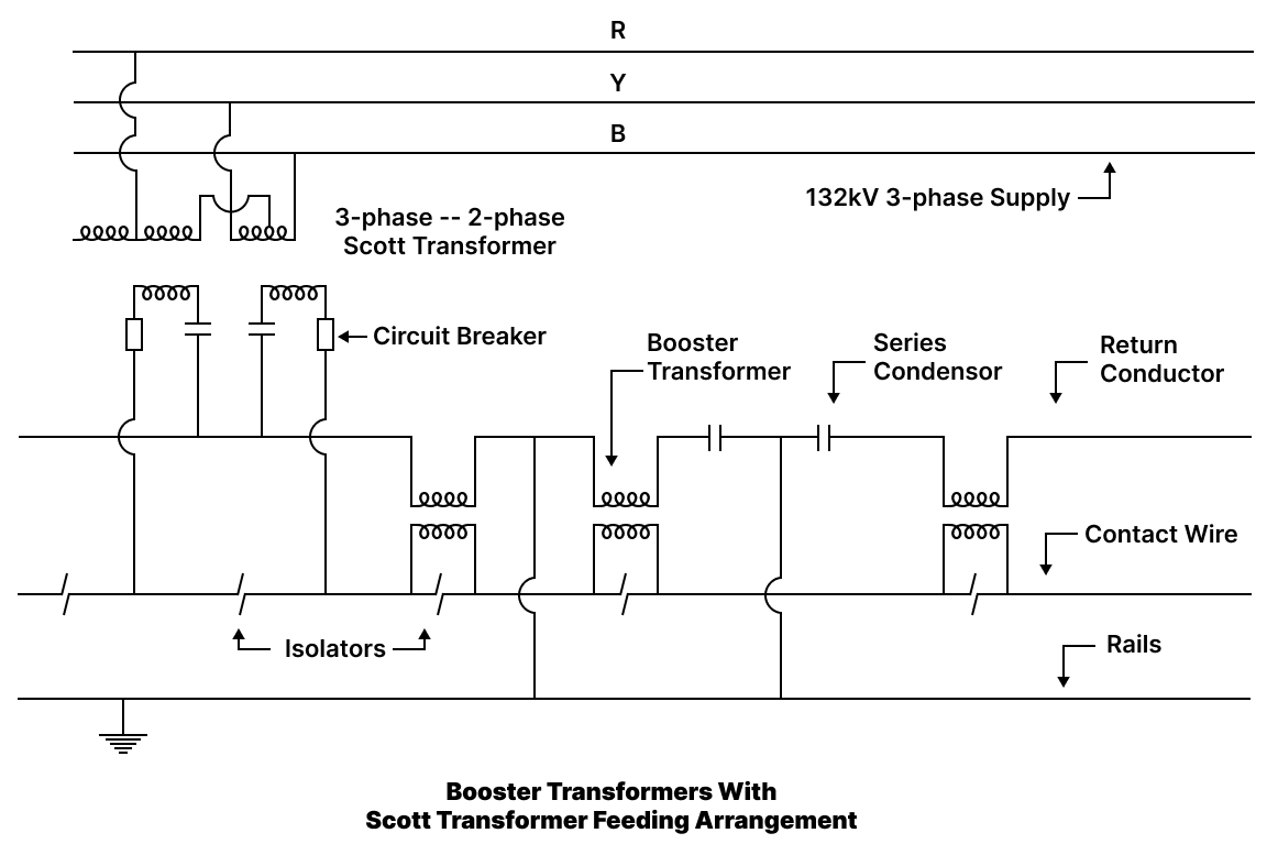
Normally single-phase transformers are used to step down voltage from each pair of phases of the regional grid supply down to the catenary voltage. However, in a few cases Scott T-connected transformers have been used to convert the 3-phase supply to the single-phase power needed for the catenary. Below is an example of how this works, shown in the context of a section provided with booster transformers and a return conductor as well. Scott transformers were used on the Bhusaval-Igatpuri line and elsewhere.
Electrical Parameters of AC OHE system
Traction Supply Voltage
Nominal Voltage: 25kV
Permissible Limits: 19.9kV to 27.5kV (17.5kV for Mumbai EMUs)
Traction Supply Frequency
Nominal: 50Hz
Permissible Limits: 48.5Hz - 51.5Hz
Loop Impedance of OHE with Earth and Rail Return
Single Line: 0.41∠70°Ω/km
Double Line: 0.24∠70°Ω/km
Traction Transformer Rating: 13.5MVA
Traction Transformer Resistance: 0.179Ω
Tranction Transformer Reactance: 5.49Ω
Harmonics in Traction Current with Silicon Diode Locomotives
3rd Harmonic - 150Hz: 38.5% at 142A, 11.5% at 480A
5th Harmonic - 250Hz: 14.35% at 142A, 5.48% at 480A
7th Harmonic - 350Hz: 15.0% at 142A, 2.0% at 480A
Average Power Factor: 0.7-0.8
(this was before 3-phase locos were introduced in large numbers)
Catenaries
IR uses catenaries of the constant-tension type. At one end of each section of the catenary the cable connects to a pulley block or winch system which then connects to a cable that goes over a pulley and is terminated by a hanging counterweight. The pulley and weight combination ensures that the catenary cable maintains the same tension regardless of the ambient temperature and the consequent expansion or contraction of the cable. This avoids problems with the catenary sagging too much in hot weather, or, if the tension is too high, snapping in cold weather. The pulley block or winch arrangement provides a suitable reduction ratio between the change in the catenary's length and the distance the counterweight moves. A reduction ratio of about 5 is common.
The tension of the catenary cable in most cases is kept close to 1000kg at 35°C. Maximum tension length for the catenary is 2000m, although in practice it is usually shorter. It is important that the tension be within certain precise bounds for mechanical reasons: the moving pantograph creates a shock wave in the catenary that travels along the cable; its speed (the critical velocity) is determined by the tension in the catenary, and if it is less than the speed of the pantograph, the cable will be prone to buckling and snapping, or else the pantograph loses contact with the wire as it oscillates in resonance, and current collection fails. For this reason the tension also has to be set so that the critical velocity is higher than the maximum speed of trains on the section. The pressure of the pantograph pan against the contact wire is usually around 6.5kg/cm2 on IR.
The equivalent copper cross-section of the catenary is usually about 157 to 165 sq. mm. (65 sq. mm. stranded copper-cadmium catenary and 107 sq. mm. grooved copper contact wire). On a single-track section, this allows a current of up to 600A to be drawn from the catenary without raising its temperature to more than about 85°C, which is the safe upper limit to avoid risks of fire, equipment failure, etc., and to maintain the physical properties of the catenary within acceptable bounds. On the Waltair-Kirandul section which sees extremely heavy ore traffic, and some other busier sections catenary equivalent cross-sections are up to 200 sq. mm, whereas loops, spurs, sidings, etc. often have lower-capacity catenaries with equivalent copper cross-sections of 107 sq. mm. For reference, note that a BG loco in typical operation may draw about 120A, and in the past, an MG loco about 80A.
Catenary contact wires are usually made of processed copper or copper alloys. Pure copper has high conductivity, but does not have the desired tensile strength, and hence it is often processed or alloyed in some way. Annealed copper has a tensile strength of about 25kg/mm2. Hard-drawn copper has a tensile strength of 42kg/mm2, while cadmium-copper has a tensile strength of 63kg/mm2. Other materials such as bronze have also been used for contact wires.
DC traction sections had much higher equivalent cross-sections because of the higher current drawn (as the voltage is about 1/16 that of AC sections, the current is correspondingly higher, necessitating a total catenary cross-section about 4 times that used on AC sections). Typically, the equivalent cross-section for DC catenaries was about 645 sq. mm (323 sq. mm primary catenary cable, 129 sq. mm auxiliary catenary, and 193 sq. mm contact wire).
As mentioned earlier, the catenary in fact consists of more than one cable; the one that actually touches the pantograph and carries the current is the contact wire.
The contact wire may be suspended directly from the cantilever arms from the support posts (this is not common, and is only found on low-speed sections and turnouts). More often, the contact wire is suspended from another wire called the messenger wire. The messenger is the one that assumes the typical catenary (hyperbolic cosine) curve shape. The contact wire is suspended from the messenger by vertical risers or spacers. A third wire, the auxiliary cable may appear between the messenger and the contact wire although this design is rare in India.
The contact wire is usually grooved on the sides, so that it can be gripped firmly from the sides without creating any discontinuity on the lower surface where the pantograph rubs against it. It is usually made of hard-drawn copper, although sometimes copper alloys have been used. The other part — the catenary cable — is made up of multiple strands of copper, or more often, a copper-cadmium alloy. In 1990, IR experimented with installing aluminium contact wire catenary on a 260km section in the formerly SER section between Durg and Nagpur. This proved to be unworkable because there were too many defects caused by oxidation and mechanical failure (strand breakage) in the wire, and the aluminium cables were replaced by standard copper-cadmium wires by 1998. The messenger wire is usually of an alloy chosen more for its mechanical properties as it does not need to conduct the traction current. WR used 2 current-carrying cables and more closely-spaced substations to power its 1.5kV DC catenaries; CR used 3 current-carrying cables and substations that are farther apart.
The stagger of the contact wire refers to the distance between it and the pantograph's mid-point. The stagger must be kept within acceptable limits to prevent damage to the OHE and the pantographs, and this requires careful layout of the contact wire on curves and turn-outs or crossings, and the provision of stabilizing connectors in areas with lots of wind or uneven track that causes the pantograph to bounce up and down. Note that in order to even out the wear on the pantograph contact wires are usually arranged in a zig-zag patter within a certain range of stagger.
Catenary Height
For a vast majority of electrified lines, the contact wire is generally at about 5.5m from the rail level. The minimum height is around 4.8m (e.g., under bridges or overpasses, etc.). In yards, in sheds or lines leading up to sheds, etc., the catenary contact wire may be higher; 5.8m is a typical height.
The Western Dedicated Freight Corridor and some sections of IR's mainlines (Viramgam - Mahesana - Ajmer - Ringas - Rewari) feature high-rise catenaries to enable double stacking of containers without the use of well wagons. These catenaries have a maximum height of 7.1m.
At the end of each section of catenary, a new section begins, with the old and new catenaries running in parallel for a short distance. On BG routes, this switch from one catenary to another usually happens over a length corresponding to 4 catenary masts, with the old and new catenaries overlapping (running parallel) for about 50m. On MG, this was usually accomplished over a length corresponding to 3 catenary masts, with one catenary taking off immediately after the point where the other stops.
When successive sections of the AC catenary are supplied by different phases from the 3-phase power grid, there is a short, electrically neutral (un-energized) section (dead zone or neutral section) of catenary that comes between them. The loco has to coast through this 'phase break' with a brief interruption in the supply of power. Sometimes different sections of the catenary are connected to different phases at different times and the neutral sections may be a switched neutral section. (The term also refers to neutral sections at AC-DC switchover points where the neutral section can be switched to either the AC or the DC supply, and is also known as the dynamic neutral section.)
In DC catenaries, there were similar breaks (power gaps) with neutral sections at points where adjacent sections of catenary were supplied by different substations. Neutral sections used to be quite long (41m was a common length) but now many neutral sections corresponding to phase breaks in the AC power supply are as short as 5m. Some locomotives are also being provided with modifications to keep their headlights and some auxiliary equipment turned on while traversing the neutral section. Refer the previous page on how IR locomotives handle these phase changes.
Control and Monitoring
A Remote Control Center (RCC) is located at or near the divisional traffic control centre. The RCC has the control and monitoring equipment for the electric traction in the areas controlled by the traffic control centre. Prior to 1980, IR used an electromechanical control system, Frequency Modulated Voice Frequency Telegraph (FMVFT). Since 1980, IR has been installing a microprocessor-based system called 'SCADA' (Supervisory Remote Control and Data Acquisition System) for remote control of electric substations and switchgear. A central SCADA facility (the division control centre) can control a region extending to about 200-300km around it. SCADA allows remote monitoring of electrical parameters (voltage, current, power factor, etc.) in real time and remote operation of switchgear, as well as automatic fault detection and isolation, allowing better control of maximum demand, trouble-shooting, etc. SCADA replaces an older system that used electromechanical remote control apparatus.
For some information on overhead equipment inspection vehicles, see the section on self-propelled vehicles.
Miscellaneous
Q. How does regenerative braking work?
Regenerative braking works on the principle of converting the kinetic energy of the locomotive (and train) back to electricity by using the traction motors in reverse (as generators) and feeding the electricity back to the OHE. This is somewhat easier with DC than with AC traction as with the latter the phase and frequency of the generated electricity have to be matched to that of the OHE. On the other hand, regeneration with DC motors adds to their bulk and complexity.
The newer AC locos have microprocessor control which helps enormously as the waveform and phase of the regenerated power can be adjusted precisely. The regenerated voltage is in effect the loco presenting a negative load to the OHE system, which manifests itself as a slight rise in the system voltage. This results in a corresponding reduction in energy supplied by the generating units on the grid, and the regenerated energy can, in principle, even go back to the supplying grid and be used elsewhere.
The OHE is said to be receptive if it is in a state where the loco can use regenerative braking. If there is no other loco on the section that can absorb the power, and if the substation is not set up to send power back to the supply grid, regeneration results in the OHE voltage rising more than a certain threshold -- this is how the control systems on board the loco can detect the (non-)receptivity of the line. If the line is not receptive the loco has to resort to using frictional or rheostatic braking.
Even if the line is receptive, feeding power back to the supply grid may not always be possible, though, because of practical constraints in the design of the substation equipment, reverse flow detection relays in the supply grid (provided as protection in case of a fault in the 132kV supply system), improper phase match by the loco resulting in relays blocking the regenerated power, etc. The regenerated power therefore often gets used just by circulating in the OHE system and thereby getting used by other locomotives in the section. Because of this, regenerative braking bears fruit in busy sections where there are always some live locos. (In other railway systems, e.g., in Japan, although not in India, sometimes the regenerated power is just dissipated using large resistive loads at the substation or elsewhere.) Conversely when the system voltage starts dropping, it is an indication that the locomotive(s) on the section is/are not generating power and are instead consuming power (the normal case) in which case the normal power supply feeds energy back in to the OHE.
Apart from saving a fraction of the electricity costs for the railways, regenerative braking in practice also offers the driver finer control over braking a train, and the savings in brake pads and other equipment used in normal frictional braking is also significant. It has been claimed that regnerative braking in busy sections can save up to 10% or more of the electricity costs.
Q. What are the ‘notches’ and ‘transitions’ of the traction motors?
There are typically several (4 or 6) traction motors in a locomotive, depending on the number of bogies and the number of motors per bogie. They can be grouped in the electrical circuits in various ways, such as being all in series, a series combination of pairs in parallel, or all parallel, etc. These combinations provided a few different ranges of power/torque and speed. Within each such combination, finer control over the speed and power is possible by resistive (rheostatic) control, chopper (SCR - semiconductor switches) control, or by frequency control as in the 3-phase AC locos. Most older locos used resistive control with a large array of resistive elements that could be progressively added into or taken out of the circuit to limit the current drawn by the motors.
Each step in this is a ‘notch’. E.g., the WCAM-3 loco operates with its 6 motors in series, with notches numbered 1 to 22; at a higher speed it can use either 2 series sets of 3 paralleled motors or 3 series sets of 2 paralleled motors each, with notches numbered 23 to 32; and finally with all motors in parallel (with the full voltage available across each), with notches numbered 33 to 39. A transition notch is the circuit setting where the motors are being switched from one grouping to another (e.g., series to series-parallel).
Note: This applies not just to electric locos; the traction motors in a diesel-electric locomotive also have such controls.
Q. What happens if the power fails when a loco is running? What happens if the wrong pantograph connection is made (DC circuit for AC catenary or vice versa)?
For most loco classes, loss of power in the OHE is sensed automatically and the main electrical circuit from the pantograph to the traction equipment is disconnected. A lamp ('LSS') glows on the control panel indicating loss of catenary voltage (in addition, of course, to all the voltage and current gauges going dead), and in some locos a warning buzzer also sounds. The main circuit breakers (DJ, DS) open, all the auxiliary equipment is reset, and the master controller reverts to the zero notch position automatically. A similar sequence of events occurs if the wrong pantograph circuit is used (DC for AC or the other way around), in the dual-power locomotives (see below). Of course, once the main circuit breaker is open and the loco is unpowered, it will coast to a halt, and all that the driver can do is to apply the brakes to control the stop. The loco needs to be powered up again as if starting up from scratch. (See energizing a dead loco for more details.)
In the past, dual-power locos (WCAM-x, WCAG-x) had DC equipment and different pantographs for a particular power supply. The pantograph selector switch had five positions: E, DC, O, AC, and E. The central 'O' setting is the off position. 'DC' raised the DC pantograph and 'AC' raises the AC pantograph. The two 'E' settings at either end are emergency settings, for using the DC pantograph under AC traction or the AC pantograph under DC traction. If one of the 'E' settings was not used and the wrong pantograph was raised, a voltage sensing device (VSD) triggered and brought the pantograph down immediately. Note that normally current collection from the pantograph does not start immediately when it comes in contact with the catenary -- there is a gap of a few seconds, intended to allow the VSD and other safety devices time to act. The VSD itself consists of a potential transformer with a resistor connected in series with its primary at one end and grounded at the other end. Two relays, QAC for AC and QDC for DC, controlled the position of the pantograph. QDC was energized when the DC pantograph was raised and DC supply was sensed at the OHE; QAC is energized if the AC pantograph is raised and AC supply sensed at the OHE; if the wrong supply is sensed, the relays are de-energized and the pantograph lowered. There are also slave relays for interlocking. These relays operate off 110V batteries. The electro-pneumatic switches that control the main traction current flow (DS or Disconnecting Switch for DC mode, and DJ or Disjoncteur for AC mode) are themselves energized by the relays governed by the voltage sensing devices. Thus, the main traction current path is also immediately interrupted and no current collection can occur if the wrong pantograph is raised. In emergency mode, the current paths were changed to allow DC traction current to flow from the AC pantograph or AC from the DC pantograph.
With DC equipment being disconnected in these locos, many relays and switches have been removed and dummies placed in their position.
Q. What are the ‘ignitrons’ and ‘excitrons’ that the early electric locomotives used?
These are different kinds of rectifying devices used to convert alternating current to direct current. In the early days, this could be done only with vacuum-tube technology as semiconductor technology could not handle the high voltages and currents that need to be switched in an application such as in a locomotive.
An excitron is a mercury vapour rectifier which uses a pool of liquid mercury as its cathode. An arc is maintained between this cathode and an auxiliary excitation anode, which maintains a concentration of ionized mercury in the tube. Current flows between the main anode and the cathode by mercury ions only when the main anode is positive with respect to the cathode.
An ignitron is also a mercury vapour rectifier. However, in this an arc is not maintained continuously between the anode and the cathode. The arc exists while the anode is positive but is extinguished as the polarity switches. Instead, an igniter electrode of a semiconductor material such as silicon carbide is kept partly dipped in the mercury pool cathode to initiate the arc when the anode goes positive.
Developments in solid-state devices have allowed the use of semiconductor rectifiers instead of the more capricious and fragile vacuum-tube rectifiers in today's locomotives.
Q. Where can I learn more about electric traction?
More information can be found on the web and elsewhere. For a start, try these FAQs and glossaries.