Train Working Systems – Interlocking
On this pageNote: Information on this page regarding operations and working using physical keys and ball token systems are historical and are provided only for the sake of completeness. Almost all of IR now uses panel based route relay and electronic interlocking.
Train Working & Interlocking: General
Q. What kinds of signalling and train working systems are in use in India?
The absolute block system is the most widespread method of train working on IR. The block sections may be handled manually or automatically, or by some combination of those. In the past, there was widespread use of physical token systems such as the Neale’s Ball Token instruments, but these have now been phased out and are found only in isolated branches.
Other than the block system, some other special-purpose methods of train working are used in some circumstances. Multiple aspect colour-light signal systems are the most commonly used signalling type, but semaphore signalling was in widespread use until the late 1990s.
AWS (Automatic Warning System) is an in-cab signal warning system used in suburban EMU systems, primarily Mumbai and Howrah. It was proposed for main lines including New Delhi - Agra, Howrah - Mughalsarai, etc. However, early trials on the Howrah - Mughalsarai stretch did not succeed as the track-side magnets and other equipment were subject to theft and vandalism.
Recently, IR has begun rolling out a system called TCAS (Train Collision Avoidance System), an indigenous solution comparable to the European Train Control System (ETCS). ETCS was proved to be too expensive for widespread use in India. Trials have been successful in the Lingampalli – Vikarabad – Wadi and Vikarabad – Bidar sections of SCR, so plans are underway to implement this system across all major traffic dense sections covering about 2000km. Initial rollout will be in the suburban areas.
A few areas have seen the introduction of forms of centralized traffic control (CTC) in conjunction with automatic colour-light signalling. (CTC was first introduced on the NER’s busy then MG section between Gorakhpur and Chupra, and later on the Bongaigaon-Changsari section of NFR.) The suburban section of Madras Egmore - Tambaram also has CTC. A large CTC at Tundla was also setup to manage traffic between Ghaziabad and Kanpur, though the current coverage is about 250km out of the total 400 or so. 12 more CTCs across many zones were sanctioned in 2020.
A Train Management System (TMS), from Bombardier, is used on the Mumbai suburban system (Churchgate - Virar) which provides centralized online monitoring and reporting of train positions. (12/2021) TMS work on Khurda Road Division of East Coast Railway is in progress and is expected to cover more than 800km.
The Delhi Metro system uses Continuous ATC (CATC) including ATS and ATP on all its sections. (12/2021) The Pink Line (Majlis Park to Shiv Vihar) and Magenta Line (Janakpuri West to Botanical Garden) have full ATO, though staff is present to attend any other emergencies. A portion of the underground section of the Yellow Line was the first to get ATO around 2006, though a modified version. Drivers were still on board to open and close doors etc., but all normal train operations were handled by the ATO. This early system was supplied by Alstom.
Around Chennai, several suburban stations have their signals automatically controllable from Basin Bridge using a fault-tolerant system that interconnects the signalling of up to 32 stations using a dual fibre-optic ring. This system also provides for 6 voice channels for communication among these stations. This system was developed indigenously by SR, the Dept. of Electronics, and IIT Madras. (12/2021) Currently, it is not known whether this system is still in use.
Most points and interlockings are electrically driven by motors, but at smaller stations, yards and sidings, some lines maybe worked mechanically (rod or pipe linkages are common, but earlier, double-wire systems were also used). Many points exist which have to be manually operated at the location of the points after using a key to unlock the points.
Following British practice, IR’s signalling is essentially route signalling where the signals generally indicate which route has been set for a train, letting the driver choose the speed as appropriate for the divergences, curves, etc. (as opposed to speed signalling which is the basic philosophy underlying American practice). Of course no modern system of signalling is purely route-based or speed-based, and there are elements of speed signalling in some of IR’s signalling as well.
Q. What is ‘isolation’?
Isolation refers to methods of protecting one line from the adjacent lines, e.g., in the case of loop lines that branch out from the main line at a station. A train or any rolling stock that is stopped on one of the lines while another train is moving through on the adjacent line should be prevented from moving and running over the points to the main line or fouling the adjacent line. There are several methods adopted to ensure isolation. Haye’s Derails (which guide the flanges of wheels over and across to the outer side of the rails to derail a moving vehicle), Scotch Blocks (which prevent points from being set for vehicles on the loop line to be sent to the main line), and similar devices are sometimes used (more so in the past - these are less common now). More commonly now, derailing switches (points that deliberately take the moving vehicle off the line and derail them) or points that lead to sand humps or sidings are used. Derailing switches or points to sand humps, sidings, etc., can also be interlocked (see below) so that they are automatically set to isolate the line when signals are taken off for the adjacent line. In addition, sometimes these switches have sensors so that unintended movement over them automatically bring signals on all adjacent lines back to danger.
Q. What’s the ‘clearing point’ or ‘fouling point’ or ‘fouling mark’? What is ‘overlap’?
The clearing point is the point ahead of a stop signal up to which the track must be kept clear of obstructions in order for a train to be accepted from the rear of the signal. In most cases this is with reference to home or outer home signals guarding entrance to station limits from a block section. The distance from the stop signal to the clearing point is the overlap (also overrun, or clearing distance).
The overlap is 180m with MACL (or MLQ or MAUQ) signalling, where distants or warners protect the approach to the stop signal. In the past when lower-quadrant or 2-aspect signalling was more common, this overlap was 400m. No trains may be parked to the rear of the clearing point on the track protected by the stop signal. This provides a margin of safety in case a train overshoots a stop signal which is on, because of brake failure, driver inattention, etc.
The fouling point or fouling mark is a point to the rear of a converging junction, such that a train must be to the rear of that point in order to ensure that any train moving on the other converging line can proceed without being obstructed.
Stop signals guarding convergences are usually placed some distance to the rear of the fouling point for the junction; this distance is also known as the overlap, and again, provides a margin of safety against trains overshooting the stop signal. A similar safety distance is maintained ahead of the last stop signal of a station, before pulling off signals for a departing train; this is usually 120m or so.
Fouling points are usually marked by a stone or cement slab with ‘FP’ written on it by the side of the tracks.
The fouling point may also be marked for a siding to indicate that a rake must be stopped beyond it in order to avoid obstructing other trains passing by on the through tracks or on to other sidings. A number on it indicates the number of standard coaches or wagons that may be safely stabled on that siding.
Q. What are the last-vehicle indications that IR uses?
The last vehicle of a train is supposed to carry a blinking, electric red lamp at the rear. Earlier, the requirement was for merely an oil lamp, which was often missing or very feeble.
Last vehicle indications are of different types. A large ‘X’ is often seen painted on the rear of the coach that is the last one. In addition, a small board with ‘LV’ (white on red) is often attached to the rear of the vehicle (it stands for Last Vehicle). In the past the rear of the coach had a set of concentric circles. EMU/DMU rakes had a series of diagonal strokes painted on. The ‘LV’ board also had different colours (black on yellow).
Ad hoc indicators such as red flags or banners are sometimes also used on engineering or works trains or multiple locos running light.
If a train passes by a station or signal cabin without the appropriate last vehicle indication (or without confirmation of the number of coaches or wagons as mentioned above), it is assumed that the train has parted and suitable emergency procedures are brought into play.
There are some cases where a Last Vehicle indication is not required – for instance, when the number of coaches or wagons in a train can be passed on to each block section after verification from the previous block section at the time the Line Clear indication is obtained (and with exchange of private numbers). The information is also provided to the section controllers. In some cases when working entirely within one block section, an ‘LV’ sign is not needed, if the number of coaches or wagons is communicated telephonically to the next station.
Q. What’s ‘interlocking’?
In order to ensure that the signalling system never provides unsafe (conflicting) signals and the points are not set for more than one train that might end up proceeding on to the same section of track and hence suffering a collision, various schemes have been developed to coordinate the settings of the points and the signals within the region controlled by a signalbox or signal cabin.
The vast majority of IR’s interlocking is electrically driven these days. The points and signals are worked from one integrated mechanism in a signal cabin which features a display of the entire track layout with indications of sections that are occupied, free, set for reception or dispatch, etc. The interlocking is accomplished by electrical circuitry – relays and switches in older electrical or electropneumatic systems, and computerized circuits in the newer fully electronic systems.
Electrical interlocking
Panel Interlocking (PI) is the system used in most stations on IR. In this, the points and signals are worked by individual switches that control them.
Route Relay Interlocking (RRI) is the system used in large and busy stations that have to handle high volumes of train movements. In this, an entire route through the station can be selected and all the associated points and signals along the route can be set at once by a switch for receiving, holding, blocking, or dispatching trains.
Solid State Interlocking (SSI) is similar to RRI, but the interlocking is achieved by electronic circuitry instead of electromechanical relay systems. They are in use on a few busy junctions and large, complex yards.
Electronic Interlocking (EI) is the modern update to SSI. It uses a fully software driven approach to setting routes, eliminating almost all relays, reducing complex wiring and interconnections etc. Because it is software driven, diagnostics in case of failures are easier to identify. Layout changes and remodelling don’t require a change in wiring, just updates in the software and output configurations. IR has begun rolling out large EI at extremely busy stations like Kharagpur, Tundla, Jolarpettai, Hubli etc. Panel interlocked stations due for upgrades are now being moved to EI.
Mechanically operated interlocking
These schemes coordinate the positions of the levers controlling the points with the signals governing that section of track and connected branches, loops, or sidings. Until the 90s, these were the most common type of interlocking found on IR’s less busy routes.
For instance, in one common mechanical scheme, a key that allows setting the points for a route has to be obtained from the block instrument, and as long as the key is removed the instrument cannot be set to provide Line Clear for a conflicting route. The wires that operate signals, and the rods that control points, are all interconnected in the lever frames at the signal cabins so that they are literally ‘interlocked’ – the position of one lever or key physically obstructs the movements of other levers and keys which control points or signals that can be set in conflicting ways.
Manually operated interlocking
This is a form of mechanical interlocking as well, but relies on the signalman to move about from one set of points and signals to another carrying with him the keys used to operate them. At small stations and on less busy branch lines various forms of manually operated mechanical interlocking were widespread even in the mid-2000s. At points controlling catch sidings in hilly areas, often the interlocking is manual where the driver has to use a key provided by the stationmaster or signalman of the last station before the siding – the key is inserted into the interlock box which notifies the signal cabin and the points are then set for the main line and the signal is pulled off, giving the train authority to proceed. (This system is common in many hilly areas, although busier lines with catch sidings are being provided with automatically operating delayed signals where the points are controlled by a timer and are set to the main line only after the train has halted for the prescribed period of time.)
Even as of the late 1980s one had only to go a few kilometers outside any big city along a railway line to spot tiny signal cabins or block huts along quiet lines where all the action was done by the signalman unlocking and locking points and pulling off signals after talking on the magneto-telephone to his counterpart at the next signal ahead.
Hepper’s Key Transmitter Instruments and similar key dispensing instruments were in wide use for operating points manually. Depending on the state of the block instrument and the interlocking set up for the local layout of lines, these instruments would dispense a key only when the appropriate combination of signals had been set; the key would then be used to unlock points to divert a train on to a loop, for instance – and while the points were so set, that key would not be released and the signals could not be changed. Hepper’s Key Transmittters and other key interlocking systems (Annett’s Key, etc.) allowed for operating interlocked ground frames and points outside the range of direct mechanically connected operation.
A common system in use was Sequential Key Interlocking, which saved on the installation of point rodding and instead relied on the signalman walking over with a key to lock or unlock points. As an example, consider a station with a main line and a loop line. To receive a train on the main line, a key is inserted into the signal frame in the cabin or platform, which allows the Outer and Home signals of the station to be pulled off.
In order to receive a train on the loop line instead, the key is used as before to pull off the Outer signal, but the Home is kept at danger. Instead, when the train has stopped at the Home signal the key is removed and taken to the facing points for the loop. The same key unlocks the points so they can be set for the loop; it also releases another key which has to be taken back and inserted in the signal frame at the platform to pull off the Home signal to let the train advance on to the loop.
The mechanism was such that only one of these two keys could be released at once; the second key did not allow the operation of the Outer signal, and it had to be taken back to the facing points of the loop in order to release the first key.
Regardless of whether the mechanisms are controlled manually or by electronic circuits, and whether they are operated mechanically or electrically, all interlocking schemes usually enforce several or all of the following rules:
- No signal can be pulled off unless corresponding points are set correctly.
- Facing points are locked to the corresponding route when a signal is pulled off.
- Signals for conflicting movements cannot be pulled off simultaneously.
- Points for conflicting routes cannot be set simultaneously.
- Trailing points are locked to the rear when a signal is pulled off.
- Distants, warners, repeaters, etc. cannot be pulled off unless the corresponding stop signals are pulled off.
- Gate stop signals cannot be pulled off unless level-crossing gates are blocked to road traffic.
The description of the possible routes that can be set, and the corresponding dispositions of points and signals are found in the locking table and selection table for a station. The locking table lists the signals and points controlled; the levers at signal boxes (or control panels at control centres) which operate various signals and points; which signals and points are locked (and in what position) when other signals are pulled off or points set; which track circuits are clear or occupied; etc.
The selection table lists the allowed non-conflicting routes that can be set. The terms route selection, route locking, route holding, and route release are used to describe the various steps in the process of picking a route for a train.
In various semi-automated systems of interlocking the electrical or electromechanical mechanisms or the electronic circuitry takes over a large part of the bookkeeping details that determine the sequences in which signals must be pulled off or points set to assign a route to a train. In the more primitive mechanical interlocking systems, such a sequence has to be manually followed; for this purpose the locking and selection tables are used by the signalman, along with lever leads which indicate for each signal lever which other levers must be set or cleared.
Q. What are the different levels or standards of interlocking that IR specifies for stations?
There are three levels of interlocking used by IR.
A Standard I interlocked station has mechanical interlocking. It also usually has just one running line and a loop line (and perhaps a couple of sidings). These are usually branch line stations. The points are worked by point levers situated near the points, and the signals are worked from interlocking frames in the signal cabin. Key locking (see above) is used, but the mechanism is such that a key obtained from the points mechanism after setting the points for one route must be used on the signal post locking mechanism to pull off the corresponding signal(s) and also to operate the block instrument, thus interlocking the signals and points. All signals must be operated from the same interlocked frame on the platform, under the station master’s control. Through running speed for trains is restricted to 50km/h. An Outer signal must be provided, as must a bracketed Home signal to give drivers indication of whether the train is being received on the main line or a loop line so they can regulate its speed appropriately. Starter signals are optional. The main line does not have to be completely isolated from the adjacent loop lines.
A Standard II interlocked station may be mechanically or electrically interlocked (usually the latter). These are usually non-trunk main line stations. The main running line at such a station can be completely isolated from the loops and shunting sidings on both sides. In mechanical interlocking, plunger locks or other similar mechanisms must be used to keep the points locked in position when set for a route. Plunger locks may be operated from the cabin, or line-side. In electrically interlocked systems, setting the points activates electrical circuitry that enables or disables the appropriate signal levers and block instruments. A Warner or Distant signal must be provided, along with an Outer and a bracketed Home. Starters are optional, although if there is no starter the Warner must be locked with the block instrument. The signals may be operated from the platform under the station master’s control or from a cabin. Through running speed for trains is restricted to 75km/h.
Standard I and II stations sometimes do not have starter signals, only home signals for receiving trains; in such a case trains are dispatched using flag or lamp signals from the station. Standard I and II stations usually have only one signal cabin.
A Standard III interlocked station has points and signals that are either interconnected mechanically within the same mechanism, or electrically as with route-relay and panel interlocking. These are usually stations on trunk routes. Usually two signal cabins whose signal and points controls are interconnected are provided. These stations usually have the full complement of signals including warners or distants, outer and bracketed home signals, and also starter signals, for receiving and dispatching trains. (Advanced starters are still optional.) All points must be operated centrally, or in coordination between the two (or more) interconnected cabins. Through running speed for such stations is limited only by the speed limit for the section. The loop lines at such stations have to be completely isolated from the main running line by means such as sand humps, over-run lines, trap points, or derailing switches, etc. In some cases, especially with signals and points too far from the station building for direct mechanical operation, the operation of remote points and signals is dependent on keys provided by the Station Master; without the key the point or signal lever cannot be operated. Interlocking is ensured by having the key dispensed from a key instrument that is connected to the block instrument under the Station Master’s control. Common key dispensing mechanisms were the Hepper’s Key Instrument, the Electric Slide instrument, and the Interlocked Key Box. In other cases, the block instruments may be located in the cabins, but the signals controlled directly by the Station Master.
Standard III.I (or III/I) is another designation found for some stations, which indicates that the station is rated as for Standard III, but the loop lines are not physically isolated on one side of the station. Similarly, a Standard II.I (or II/I) station is rated as in Standard II, but has loop lines or sidings that are not completely isolated on one side of the station.
Block Working classification of stations Stations are also classified as ‘Class A’, ‘Class B’, etc. See the classification of stations based on block working methods for more information on this.
Q. How are non-interlocked (NI) stations operated?
Non-interlocked stations are what their name implies: there is no interlocking of any kind. The points have to be set appropriately and locked manually before pulling off a signal. The station master is personally responsible for ensuring that this is done and is supposed to have the keys to unlock the points with him or under his control. Trains are restricted to 15km/h over station limits. Non-interlocked stations are found only on sections with very light traffic. The most basic version of non-interlocked stations have truly no arrangement for controlling the points in relation to the signals and rely entirely on the signalman or station master. Sometimes some simple mechanisms are used that provide some minimal safeguards without providing true interlocking.
Padlocked points are common at non-interlocked stations. Here, facing points are equipped with a clamp or through bolt that has a padlock that can be used to lock the points in position. To operate the points, the station master has to hand over the key for the padlock (unless the station is small enough that the station master can walk over and operate the points himself). The key is usually handed over with a badge or token indicating the route to be set, to minimize any misunderstanding in the verbal instructions. Obviously, the procedure takes time and depends on a human element for safety. The locking arrangement on the points is essential; it is not enough to just lock the lever that operates the points.
Key Locking: In this system, each set of points has a pair of keys. When the route is set one way, one of the keys is freed and the other must remain inserted at the points; when the points are set for the other route, the first key must be inserted and the other key is freed. The station master keeps the free keys in a glass-fronted box so that he can tell at a glance which routes have been set. Although this system ensures that routes are set and locked for a particular line, it does not ensure that the points have been set properly, and there is no interlocking between the signals and the points. Points may be damaged (e.g., by being trailed through) and the station master has no indication of this if he just relies on the keys in his possession. Badges or tokens are handed out as in the case with padlocked points. Key locking used with facing points (but without any real interlocking or the provision of bracketed home signals) is occasionally termed Rudimentary Interlocking in IR’s materials.
Q. What are modified non-interlocked (MNI) stations?
Modified non-interlocked stations are those where setting and locking the points releases a key which has to be used to pull off a signal; however, the block instruments are operated independently. So there is some minimal amount of a safety lock between the points and the signals, but it does not qualify as full-fledged interlocking.
Q. How are points operated?
Most points these days are electrically operated, motor driven after receiving impulses from signalling relays.
When signals are operated by single-wire transmission, points are always operated by rodding. Rodding refers to the long rods or tubes that one can see running parallel to the rails from cabins which have point levers, or from line-side point levers, and connecting with the tongue rails so that the action of the point lever moves the tongue rails to one or another position. When signals are operated by double-wire transmission, points can be operated by rodding or by wire. The principle is the same - the wire can be pulled in either direction and acts to move the tongue rails into one or another position to set the points. Rodding or wire can normally be used to operate points up to 750m, although where signalling uses single-wire transmission the operation of points by rodding is usually restricted to about 320m.
Q. What devices were/are used in mechanical interlocking?
Detector
A Detector is a very basic mechanical interlocking device that ensures that a signal can be pulled off for a route only after the points have been set correctly for it. It also ensures that the tongue rails for the points are positioned correctly (i.e., not warped to one side or another, for instance because of being damanged in trail-throughs). The detector consists of a set of signal slides that operate perpendicular to the a blade connected to the points which determine the route. The blade connected to the points has a number of notches, matching the number of signals. Each signal slide has just one notch. The notch on the signal slide fits into the notch of the point blade only when the points are correctly set for the route of the corresponding signal. When the signal slide is positioned in this way, it frees the signal to be pulled off. Then when the signal is pulled off, it moves the signal slide such that the points cannot be changed because the notch of the point blade fouls the signal slide.
Stretchers and Lock Stretcher Bars
A pair of tongue rails for a switch is often provided with two Stretchers, which connect the two tongue rails together (perpendicular to the rails). A widely-used kind on IR are known as the Williams Patent Stretchers. The front stretcher extends under the stock rail to prevent the phenomenon of ‘jumping’ or ‘dancing’ switches. If one or the other tongue rail gets bent out of shape (e.g., by a train trailing through), one or both stretchers will break. A Lock Stretcher Bar consists of an additional stretcher connected separately to the tongue rails such that if either the tongue rails bend or the front or rear stretchers break, the notches on the front or rear stretchers will foul the the blade for the detector mechanism and prevent the signal from being taken off for the route.
Plunger lock
Additionally, the lock stretcher has two notches, and a Plunger Lock, which is a bar perpendicular to the lock stretcher (and therefore parallel to the rails) fits in one or another of them, when the points are set for the corresponding route. When the lock plunger is set in one or the other notch, it prevents the points from moving. This is an additional locking mechanism beyond that provided by the detector (see above).
Often the locking is accomplished by a separate locking lever after the main lever to set the points is operated. Sometimes the locking is done in the same action as setting the points, but this is less reliable and harder to work.
Lock Bar
A Lock Bar is a long bar, corresponding to the longest wheel base of vehicles operating on the line (14m - 42’ as a minimum for BG, or 13m - 40’ for MG), provided parallel to and close by the inside of one of the stock rails, and connected to the mechanism locking the points. It is set up in such a way that when the points are set and locked, the lock bar moves vertically up until it reaches the level of the wheels riding on the rails. As long as the train is moving over the points, one or another wheel presses down on the lock bar, forcing it to be locked in position so that the points cannot be changed.
Slotting
Slotting is an arrangement for coordinating signals between two different locations (e.g., two cabins for a station), or different signals from the same location. For instance, a signal may be set up so that taking it off from one cabin requires the other cabin to release control; either cabin is able to unilaterally bring the signal back to danger. If there are two non-block cabins at either end of a station, before either one can pull the Home signal off to receive a train, the other cabin has to provide assurance that the line is clear for the adequate distance beyond the starter or trailing points in the area controlled by the cabin, as well as to ensure that points are set correctly. In that case, operating the home signal from the first cabin requires the second cabin to release the signal lever (using a slot lever in its frame) after verifying the line is free of obstructions and setting the points correctly. Another example is of a pair of signals that are operated from the same place but which need to be sequenced correctly for taking off. When the slot lever is operated so that the signal lever that it controls can actually control its signal, the term used is ‘obtaining the slot’.
A typical method of achieving slotting is to use a disengager, which can connect or disconnect the signal lever from the connecting gear mechanism of the signal wire transmission; the slot lever controls whether the disengager allows the first signal lever to engage with the connecting gear and act on the signal semaphore arm or not. Electrical slotting uses electrically activated means to achieve the same effect. E.g., in Cabin Reversers, the connection between the signal lever and the connecting gear is made through the use of a wedge that is moved electrically to notch with and connect the two, when the slot lever is operated. In Post Reversers a similar mechanism is used, except that it is the connection between the semaphore arm and its weight that is engaged by an electrically operated block controlled by the slot lever.
The term ‘slotting’ is used for electrical interlocking between signals as well.
Tappet Locking
Tappet Locking is a system used to prevent signals being pulled off for conflicting routes. Each signal lever (or point lever, slot lever, etc, in the frame) moves a plunger (also known as driving iron) either directly attached to it or through a connecting mechanism. The plungers move lengthwise. Attached perpendicularly to them are tappet bridles (also known as locking bars). Tappets are small flat bars or wedges that are attached to the bridles with cams, so that they can move slightly sideways (along the bridle). A tappet on the locking bar of one plunger presses against a different plunger. Each plunger has notches that correspond to the wedge shape of the tappets. The notches are placed in such a way that at specified configurations of the signal levers, tappets can fit into the notches. When a signal lever is moved, tappets attached to it can slide in or out of notches on other signal levers’ plungers because of their cams. However, a plunger that has a tappet from another signal lever wedged in its notch cannot move - or vice versa. Different arrangements allow for different ways to lock signal levers in pairs or groups.
Normal locking or Sympathetic locking is the case where one lever, when pulled off, locks another lever and keeps it from being pulled off. This is the case, e.g., when pulling off a home signal for the main line must lock the loop homes from being pulled off. If all the participating signals in the group are such that all of them can be at danger simultaneously, and any one may be pulled off while locking the others, it is also known as Mutual locking.
Reverse locking or Release locking is when one lever releases another when pulled. This is the case of a home signal that releases a distant signal to be cleared when it is pulled off. Two-way locking or Reciprocal locking or Back-locking is when one lever locks another in either position - considering a home and distant pair, it may be desirable to release the distant only when the home is pulled off, but then also not allow the home to be brought back to danger while the distant for it is pulled off.
Finally, Conditional locking or Special locking is possible, where one lever may lock or release another lever when a third lever is either normal or reversed. More complex ‘mechanical computations’ are possible but rare. A subtlety in the design of tappet locking signal frames, which has its parallels in locking schemes used in computer systems, has to do with the sequence in which locking and unlocking occurs. If a signal lever is moved partially, the mechanism should ensure that any locking it engages in is activated as soon as possible during the early part of the lever movement (the so-called ‘first motion’) so that another conflicting signal lever cannot be moved at the same time because the first lever has not engaged its locking tappets yet. Similarly, unlocking should happen as late as possible in the movement of the lever (the so-called ‘last motion’).
Other forms of mechanical signal interlocking have been used (e.g., tumbler locking) but tappet locking was the most common in India. Some of the concepts above apply even when the actual mechanism of achieving the interlocking is different.
Historical note: Although many manufacturers supplied signal frames to railways in India, the most common frames in British India - lasting long after other manufacturers ceased manufacturing signal frames, were those made by Westinghouse Brake and Signal Co., Ltd., referred to as ‘Westinghouse Frames’.
Q. What are Locking Tables and Pull Sheets?
A Locking Table is a table that gives the complete set of interlocking relationships among signal and point levers in a cabin. A Pull Sheet is similar, in that it conveys the same information, but is geared towards the lever operator’s convenience in showing which other levers need to be pulled for any lever. A sample locking table is shown below.
| Lever No. | Releases | Requires | Locks normal | Locks both ways |
|---|---|---|---|---|
| 1 | 2, 3 | |||
| 2 | 1 | 3 or 4 | ||
| 3 | 1,2 | 5,8 | 7,6 | |
| 4 | 2 | 6,5,8 | 7 | |
| 5 | 3,4 | 6 | ||
| 6 | 4 | 3 | ||
| 7 | 8 | 3,4,13,18,19 | ||
| 8 | 3,4,15,18,19 16 with 13 reverse |
|||
| 9-12 | Spare | |||
| 13 | 15 | 7,18,19 | ||
| 14 | 15 | 13 | ||
| 15 | 8,13,14 | |||
| 16 | 14, 8 with 13 reverse |
19 | ||
| 17 | 20 | 7,13 | ||
| 18 | 20 | 8 | 7,13 | |
| 19 | 20 | 8 | 7,13,16 | |
| 20 | 17,18,19 | |||
This example (from Introduction to Railway Operation, by Francis Da Costa) shows the locking table for a signal frame (in cabin ‘A’ at a station with two cabins, ‘A’ and ‘B’) which has 20 levers: 7 signal levers, 3 slot levers, 3 point levers, 2 point locks, and one 1 gate lock, along with 4 spare levers. The column marked ‘Requires’ shows which levers have to be pulled first before pulling any given lever. (This column by itself forms the Pull Sheet.) The ‘Releases’ column indicates which levers are released by pulling a given lever.
Lever 1 operates the Warner - before this is taken off, the main Home and Outer have to be taken off. Hence 1 requires 2 and 3.
Lever 4 is for the Loop Home. To take it off, the route has to be set and locked for the loop (6 and 5) and the gate must be closed (8). Pulling 4 in turn releases lever 2 for the Outer signal. The cross-over lever 7 is locked in normal position to avoid conflicting movements.
Lever 19 is the slot lever for the ‘B’ cabin main home signal. PUlling it releases the slot (20) for ‘B’ cabin’s warner. Lever 8 for the gate is required because the level crossing must be closed before pulling 19. To avoid conflicting movements, lever 13 for the facing points, and lever 7 for the cross-over points are locked in normal position.
Q. What were/are the cabin arrangements that were setup at stations?
With panel interlocking, cabins are no longer as important as during mechanical interlocking. Almost all control is from the station master’s office where the panel is typically located. Larger stations with complicated yards may still have cabins for better coordination with the main panel, but such arrangements are increasingly rare.
The information given below is mostly historical.
There are a few different ways that cabins can be set up for a station. Normally for a Standard III station, there are two cabins, one at either side of the station. Each cabin controls the points and signals on its side. In one common arrangement (more common in the past when relatively less experienced staff - cabinmen or levermen - were posted to the cabins), the block instruments are kept at the Station Master’s office, and the Station Master has control over the reception and departure signals (Home and Advanced Starter). The signal levers for taking these signals off and for setting the points appropriately operate only when the Station Master permits, either by direct electrical interlocking from the block instrument to the signal frames, or by keys dispensed by the Station Master. Keys may be dispensed by instruments such as the Hepper’s Key Instrument, electric Slide Instrument, or Interlocked Key Box, which are electrically interlocked with the block instruments. A later practice was to locate the block instruments in each cabin, while the signals can be controlled from the Station Master’s office. However, in cases where double-wire transmission is provided, the tendency is to keep the block instruments at the stations and not at the cabins and have more control over the signals and points from there.
Inter-cabin control: Signals and points are slotted as explained above between the cabins to coordinate their operation. For instance, for one cabin to take off the Home signal, the line has to be clear for an adequate distance beyond the Starter or trailing points, which can only be verified by the other cabin. In other cases, setting a route for the main line or loop line by one cabin is not possible without the other cabin verifying that the line is free of obstructions or that an appropriate siding is available.
Two cabins or one: Especially with double-wire transmission, all signals and points can in many cases be controlled from one central location. Having one central cabin can save on equipment and staff. However, there are some benefits to having cabins at either side of the station. One advantage is that the cabin staff on either side can check that trains are arriving intact, verifying that trains have cleared the fouling mark (this may be the duty of the guard as well), controlling level crossing gates near them, etc. More eyes watching also means that problems like hot axles or dragging equipment are more likely to be caught. Another consideration is that shunting operations can proceed slowly as all movements have to be coordinated with the single cabin and the guards and drivers of various trains, whereas with two cabins the cabin staff at either end can manage shunting operations at their ends independently. Finally, note that when the signals and points are far, generally speaking keys have to be dispensed by the Station Master for operating them; passing the keys back and forth takes time. (This can be alleviated by electrical interlocking.)
Q. What kinds of electrical interlocking equipment is used?
In electrical interlocking, the fundamental mechanisms use electric control extensively. Electrical equipment of some kinds may be used even in the mechanical interlocking systems described above (e.g., electrical relays that operate slotting). However, the basic operation there remains mechanical in nature.
Relays
Relays of various sorts are used to turn on or turn off circuits that control signals, points, slots, level crossing gates, etc. Track relays are used for track circuits (see below). Signal relays control signals.
Track Circuits
Track circuits are electrical circuits that are formed including the running rails. They are set up in such a way that when a train is on the tracks that are part of the track circuit, the circuit is altered in some way (usually, by current that normally flows in the track circuit being shunted through the conductive body of the train), thereby activating a detector which may then be used, e.g., to set signals at danger for the section.
Track circuits help with interlocked operation as they allow signals to be pulled off only if the section of track they control is safely clear of any vehicles. They also remove the human element of needing to scrutinize the track for the presence of trains that may be out of view of the signalling staff or cabinmen.
Track-circuiting is mandatory in sections where visibility is a problem, shunting operations are routinely carried out on the block section outside station limits on the main running line, or if special situations exist, e.g., if the advanced starter is more than one full train-length ahead of the most advanced trailing points of the station.
Axle Counters
Axle counters are devices that can count the number of axles of vehicles passing by them on the track. Axle counters are installed at either end of the section of track of interest; when the number of axles counted at entrance to the section is the same as the number of axles counted exiting the section, it means the train has passed through the section intact. Axle counters are used in some cases where track circuits are hard or impossible to operate (e.g., where metal sleepers are provided, making track circuit operation impossible without re-installing the track, or where conditions are such that there is too much electrical noise and conductivity problems that make track circuits unworkable).
Q. What kinds of track circuits are used by IR?
The most common form of track circuit used is the detection of a train by the closing of an electrical circuit between the two rails because of the conducting nature of the rolling stock. This circuit may use DC in the simplest form, or may use AC, at various frequencies or with coded pulses.
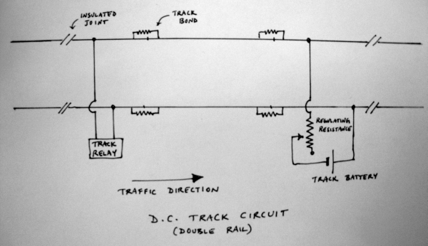
Double-rail DC Track Circuit
Double-rail DC track circuits are generally found only in non-electrified sections, and only where there is no concern with stray currents circulating in the earth or in the rails. The track circuit consists of a portion of the track which is insulated from the rest of the track by means of insulated rail joints. Within the section so insulated, bonding wires are provided to maintain good conductivity between adjacent rails. The rails on one side are insulated from those on the other by the use of wooden or other non-metallic sleepers.
The track relay is connected across the two rails at one end of the track-circuited section, and a DC power source (track battery) is connected across the rails at the other end along with a regulating resistance. When there is no train in the section, the circuit is completed through the track relay which is therefore energized. The energization of the relay lights an appropriate indicator lamp in the cabin, but may also pull a signal off for entry to the section. When a train enters the section, it shunts the current through the track relay, which as a consequence is de-energized, leading in turn to an appropriate indication at the cabin, and to signals controlling entry to the section being set to danger and locked from being pulled off. Further, note that if the track battery fails, or the bonding connectors between rails break, the relay is de-energized and these failure conditions also result in signals being set to danger.
Where traffic is (mostly) unidirectional on a line, the track relay is placed at the entrance end, so that the relay is de-energized as soon as the train enters the section, and operation of the relay is not compromised by leakage currents and other problems. Leakage currents between the rails always exist, and can reach high levels when it rains and at other times, which has to be taken into consideration when designing the circuit and its operating current values. The ballast makes a difference, with broken stone being the best and cinder being a poor candidate because it holds a lot of moisture. Ballast resistance should usually not be less than 6.5 ohms/km when wet. The resistance of the rails and the bonding wires should be less than 0.5 ohm/km.
DC track circuits of this kind are simple and cheap to install. When there are stray currents found in a region, these track circuits are often very problematic to use. Even if they are used, the presence of stray currents usually severely limits the length of the track which can be part of the track circuit.
Insulated Rail Joints
For a DC track circuit to reliably detect the location of a train within its specified section, the section must be electrically isolated from adjacent track (the exception being with jointless track circuiting methods – see below). Special kinds of rail joints are used, known as glued joints or insulated rail joints. Usually a special 940mm-long fishplate is used, with 6 holes for fish bolts. Special high tensile strength fish bolts are used and the entire fishplate and bolt assembly is glued on to the joint, including the ‘end post’ at the joint, using an epoxy impregnated fabric in multiple layers. A typical glued joint is 6.5m long and is welded to the adjoining rails. The glue and fabric ensure that the rail sections on either side of the joint are electrically separated.
Rail Bonds
At normal joints within a track circuit section, electrical continuity must be ensured. Usually, one or two bonding wires are provided that connect the two rails across a fishplated joint. This is done even though the fishplate normally provides electrical continuity, to allow permanent way operations that involve unbolting the fishplates to continue without interfering with track circuiting. Also, dirt and surface impurities can cause the bolted fishplate joint not to conduct electricity reliably for track circuiting purposes (especially with AFTC or HFTC where the impedance of the joint to the particular frequencies involved is critical).
Single-rail DC Track Circuit
In 25kV AC electrified areas, single-rail DC track circuits can be used. Rails on one side of the track are used for the the returning traction current, with adjacent rails being bonded together for conductivity. Rails on the other side are bonded together in the section of the track circuit, but insulated at either end. The track relay and track battery are connected across the rails within the track circuit section as usual, but with high impedance chokes to prevent the traction current from flowing into the relay or battery. High-voltage fuses are also provided to protect the track circuit equipment from accidentally getting 25kV across it from a downed contact wire. The principle of operation is the same as with the plain two-rail DC track circuit described above.
As a further safety measure, a high-voltage fuse or ‘interval of discharge’ (a device like a lightning protector) is provided across the rails so that if the contact wire breaks and falls on the rails, the insulated rail gets connected to the uninsulated one and is therefore earthed. The uninsulated rail on one track is bonded to the uninsulated rail of an adjacent track circuit as well, to provide a path for traction currents if the uninsulated rail breaks. Beyond the track circuit area, tranverse rail bonding connects the rails on either side together - this distributes the traction current better across both rails outside the track circuit.
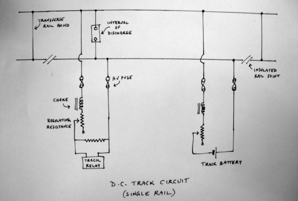
This system is simple and cheap to install, but has some disadvantages. If one insulated rail joint fails, the track circuit is effectively expanded and will interfere with the operation of adjacent track circuits. Return traction currents or stray currents cause a longitudinal voltage drop across the uninsulated rail, which limits the length of the track circuited section. Finally, in contrast to AC track circuits that use impedance bonds and double insulated rails, a single broken rail cannot be easily detected by the imbalance of return currents.
Coded Track Circuit
A coded track circuit is a variation on the simple DC track circuit, where instead of a steady DC signal, a pulse-coded current is used for the track circuit. The pulse train is generated by a code transmitter. The track relay is energized and de-energized by the pulse train, and controls the current in a decoding transformer correspondingly by switching its taps. In turn, a track detector relay follows the changing current in the decoding transformer and is configured such that it is energized as long as the specific pulse pattern is being transmitted. When the train enters the zone of the track circuit and shunts the circuit, this relay is de-energized, and signals are brought to danger. Coded track circuits have a big advantage over the basic DC track circuits in that they are much less vulnerable to stray currents.
A further advantage of coded track circuits is that different codes can be used at different times to control the signal aspects. For instance, the signal governing entry to a section of track can be set to clear or caution depending on the pulse pattern used. With any of the pulse patterns being used, however, the presence of a train will still shunt the circuit and cause the signal to revert to danger. Track circuits can also be ‘overlaid’ or have some portions of track in common. In addition, the same coded pulse trains can also be picked up by locomotive equipment by induction to provide in-cab display of signal aspects.
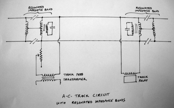
AC Track Circuit
AC track circuits use an AC signal instead of a DC in the track circuit. The frequency used for the track circuit signal is usually 83.5Hz, to avoid interference from the 50Hz traction current. Their principal advantage is that they are immune to interference from stray currents, so that they can be quite long, up to 5km or so. AC track circuits may be used on unelectrified or electrified tracks. Impedance bonds (see below) are provided for the rails at the ends of the track circuit. The purpose of the impedance bonds is to provide a path of low impedance for traction currents to flow in both rails, and to provide high impedance and therefore block the AC signalling current. A band-pass filter and rectifier are used to extract a DC signal from the AC track circuit current, for the operation of the track relay. Apart from the fact that an AC signal is used, the general principle of operation is the same as with DC track circuits.
AC track circuits tend to be immune to stray currents and hence can be more reliable, and can be quite long - a few km in length. However, the provision of a separate 83.5Hz supply makes the installation costly.
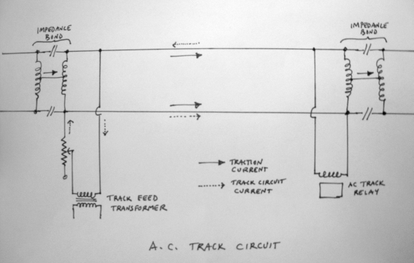
Impedance Bonds
Impedance bonds used for AC track circuits consist of two low-resistance windings wound in opposite directions on a laminated iron core. Each winding is connected across the rails on either side of the track, and centre taps from each winding are connected together. With DC traction, under normal circumstances equal currents flow in each half of each winding and if the traction currents are evenly distributed across the two rails, there is no resultant flux in the iron core. In this state, when the core is not magnetized, it presents a path of high impedance to the track circuit current. In the case of an imbalance, the core would be magnetized to saturation and the track circuit current would no longer be faced with a high-impedance path; therefore, an air gap is introduced in the magnetic circuit to prevent saturation, and the impedance bond presents high impedance to the track circuit current in all cases up to about 20% traction current imbalance. With AC traction, when the traction currents are unbalanced, the half coil that carries more current induces an e.m.f. in the opposite half coil that tends to equalize the current. So air gaps are not generally necessary for AC traction.
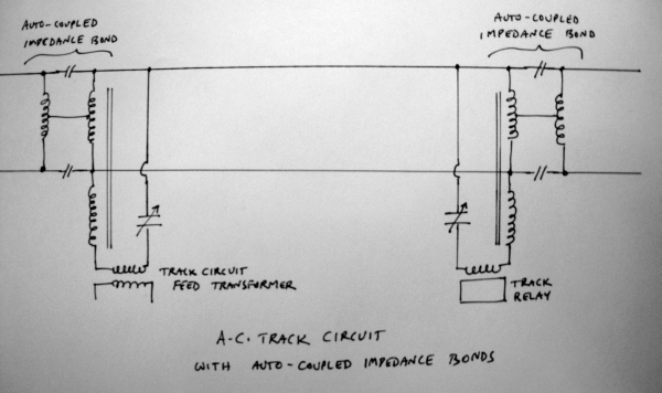
The impedance of the bond to the signalling current can be further increased by adding a secondary coil and a capacitor across it, in what is known as a resonated impedance bond. The secondary coil steps up the voltage and allows the use of a smaller capacitor than would otherwise be required. Auto-coupled impedance bonds are a modification of the resonated impedance bond idea. Here the winding across the rails in the track circuit zone forms one part of the winding of an auto-transformer, the other part having the capacitor in series. On one side of the track circuit, the other part of the auto-transformer is connected to the supply (100V) thereby being stepped down for the track circuit current, and the auto-transformer winding on the other side of the track circuit is connected to the track relay such that the track circuit current is stepped up to operate the relay. Thus, the current flowing in the bonds is usefully employed in operating the relay.
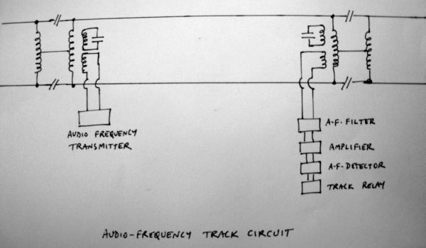
Audio Frequency Track Circuit
Most zones now have many sections that use AFTC, or Audio-Frequency Track Circuits, that are like the AC track circuits described above, but using a signalling frequency that is higher. Many frequencies are used. In early systems, 175Hz, 225Hz, 270Hz, 320Hz, and 831.33Hz were common. Multiples of 50Hz were avoided so that there is no interference from harmonics of the common line frequency for other electrical equipment or the AC traction supply. Today, there are many different systems. ABB equipment uses 1549Hz, 1699Hz, 1848Hz, 1996Hz, 2146Hz, 2296Hz, 2445Hz, and 2593Hz. Siemens equipment uses 4.75kHz, 5.25kHz, 5.75kHz, 6.25kHz, 9.5kHz, 10.5kHz, 11.5kHz, 12.5kHz, 13.5kHz, 14.5kHz, 15.5kHz, and 16.5kHz. Siemens equipment uses 1700Hz, 2000Hz, 2300Hz, and 2600Hz. A variant known as DC-coded AFTC from Alstom uses frequencies like 2100Hz, 2500Hz, 2900Hz, 3300Hz, 3700Hz, and 4100Hz.
AFTC is more reliable, especially where both DC and AC traction are in use, and allows the track circuit length to be increased a lot. The pioneers in adopting AFTC over simple DC or low-frequency AC track-circuiting were WR, SR, and CR (Dombivli, Pune-Lonavala, Chennai-Tambaram, Anand-Vatva, etc.). As with the low-frequency AC track circuits, a band-pass filter and a rectifier are used to extract the signal; however, in many cases an amplifier is needed to strengthen the signal.
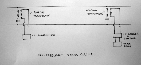
High Frequency Track Circuit
As the name implies, High Frequency Track Circuits (HFTC) use substantially higher frequencies, e.g., 40kHz, for the track circuit current. This kind of track circuit operates a little differently from the other AC track circuit types. Impedance bonds are not used. Instead, at either end of the track circuit, rail-to-rail shorts are provided. A signal transmitter that generates the high frequency signal is connected to the rails at one end using an adapting transformer, which has one winding across the rails with a capacitor in series, while the transmitter is connected across the other winding. Similarly, a receiver is connected across the rails at the other end using another adapting transformer. The transmitter and receiver connections are a little distance (5m or so) inside from the rail-to-rail shorts. The receiver usually includes a tuned filter, rectifier, and amplifier for the signal frequency.
Electrically, the track circuit zone inside the rail-to-rail shorts looks like two tuned LC circuits in parallel, with the inductance of the enclosed section of track in between them in series. The capacitors are adjusted so that the enclosed section of track is tuned to the track circuit frequency. When no train is on the track, the signal from the transmitter is received and detected at the receiver, and is used (via generation of a DC control voltage) to keep the track relay energized. When a train approaches the track circuit, it shunts the track circuit and - depending on the positions of the wheels - either de-tunes the circuit or shorts the transmitter or receiver (or both). Any of these cause the track relay to be de-energized.
In a variation on the above, the transmitter may generate pulse trains of specified duration and patterns with the high frequency signal. These are detected and converted to square waves which activate a peak detector, which in turn controls the generation of the DC control voltage to energize the track relay. In this scheme, different coded pulse trains can be used to control different signalling aspects.
The rail-to-rail shorts define the limits of the track circuit and therefore the circuit is immune to interference from adjacent track circuits. Also, the LC circuit on the receiver side can be tuned very specifically to the track circuit frequency, so that other signalling applications that use other frequencies can be used on the same section of track without compromising the track circuit’s operation.
CR was the first zone on IR to experiment with HFTC.
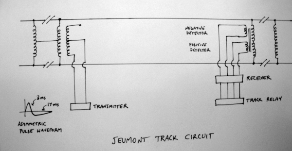
Jeumont Track Circuit
The Jeumont Track Circuit (or Jeumont-Schneider track circuit) is a design that has been tried in areas where environmental conditions make it hard to get good contact between rails and wheels, reducing the shunting effect of a train on the track.
Often, in such conditions, a higher track circuit voltage helps as the track circuit current can break down and go through thin films of oxides, salts, coal dust, scale, etc., on the surfaces of the rails. However, constant or steady AC high voltages lead to higher leakage currents and therefore waste power. In the Jeumont design asymmetric high voltage pulses with a small duty cycle are used - with a high peak on the positive side (3ms), and a low amplitude negative cycle (17ms). The pulses are emitted at about 3Hz frequency. The low duty cycle keeps power consumption low. A specialized detector rejects symmetric signals (as from the traction currents) and detects the asymmetric pulses.
These track circuits were in use at the Tambaram yards of SR, and in some areas around Kolkata. They are especially suitable in areas with DC traction (but can be used where both DC and AC traction are used) because of the corrosion problems in DC traction areas. They are also suitable for use in tunnels and other areas where oxidation of rails is more intense. As with DC track circuits, slight variants are possible for single-rail or double-rail returns in electrified or unelectrified sections. Some other variations of the basic principle exist - IR literature also refers to some designs as Pulsed High Voltage Track Circuits.
Jointless Track Circuits
The Aster Track Circuit (also referred to as Jointless Audio Frequency Track Circuit) is a design suitable for use in areas with long welded rail where impedance bonds or insulated joints cannot be provided. It uses signalling frequencies around 2.2kHz or so. An ‘electric boundary joint’ is created by connecting two capacitors in series across the rails at either end of the track circuit zone. A ‘rejector’ cable is connected from one rail about 11m outside the track circuit to the point between the two capacitors, and then to the other rail about 18m inside the track circuit. The capacitors in conjunction with the inductances of the rails and the rejector cable form tuned circuits. In addition, the transmitter for the track circuit frequency is connected across one of the capacitors. This leads to the impressed voltage being available in full inside the track circuit zone, but reduced (usually by half) outside the track circuit. The receiver for the track circuit is connected across the capacitor at the other end of the track circuit, on the side connected to the other rail. Adjacent track circuits use the same principle (the next track circuit has its receiver across the other capacitor at the end where the transmitter of the first circuit is connected.)
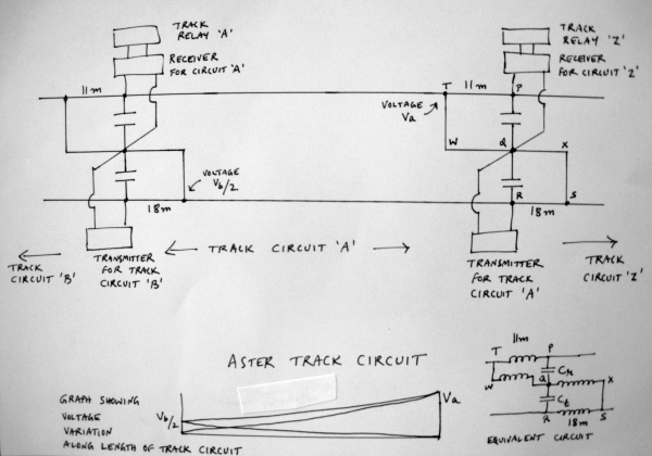
In the diagram showing the Aster track circuit, note that the lengths of rail across which the cross-connection T-W-Q-X-S are made are 11m (T-P) and 18m (R-S) respectively. This cross-connection forms the ‘rejector circuit’ or ‘electric boundary joint’. The equivalent circuit is shown at bottom right in the diagram. Note that the track circuit signal is injected across Q-R, and faces a circuit with Ct in parallel with inductances QX and RS. This circuit can therefore be set up so it offers high impedance to the signal frequency, preventing it from propagating it to the track circuit section on the right. Meanwhile, the circuit Q-W-T-P can be set up allow the signal frequency to propagate to the left.
Adjacent track circuits can use different frequencies and reduce interference by means of these rejector circuit arrangements. In addition, note that the voltage Va impressed across QR is available across TU to the left, but gets dropped (to Va/2) across the tracks on the right. The same applies to the voltage Vb applied by the track circuit transmitter for ‘B’ to the left. See the graph plotting the net voltage as we move from one end of the track circuit (‘A’, the region in the middle) to another - the voltage from track circuit ‘B’ (to the left) is reduced in half, Vb/2, on the left end of track circuit ‘A’, and falls essentially to zero at the right end of ‘A’. The voltage from track circuit ‘A’ starts at about zero on the left end, and rises to its full value Va on the right. The net voltage therefore rises as we go from the left to the right from Vb/2 to Va.
Other kinds of jointless track circuits exist, where the detection of the section occupancy by a train is done by measuring the attenuation of the signal which is at a frequency (about 10kHz, usually) which undergoes significant attenuation in rails over the distances of interest and whose propagation characteristics are known. This also means that the entrance of a train into the track circuit section is not determined precisely based on its position – instead, safety factors are incorporated in the calculations to yield zones within which train occupancy can be determined in a guaranteed fashion. The system can be made even more reliable by coding the signal in a pulse train allowing the receiver to distinguish between signals of different track circuit sections (see below).
In a variation of the jointless track-circuiting scheme, trackside units can be used to set up a resonant circuit and constrain the signal (usually between 1.5kHz and 3kHz) to a particular section of track. The advantage of jointless AFTC is clear in that insulated joints are not required, reducing maintenance, allowing the use of long welded rail sections, and eliminating the problems of insulated joint failures. Jointless AFTC sections can be 1-1.5km in length.
Coded Jointless AFTC
This system uses a mechanism such as the Aster design (see above) where insulated rail joints or impedance bonds are not needed. In addition, rather than using single frequencies for the track circuit current, coded pulse trains are used, which further reduces interference between adjacent track circuits. Jointless AFTC is in use on the Delhi Metro, and a few other places on the IR network. It was first introduced on the Tambaram - Madras Beach section of SR. AFTC equipment used by IR is from Adtranz, Siemens, US&S, and Alstom. Jointless AFTC units are manufactured in India by Medha Ltd.
Q. What kinds of axle counters does IR use?
Axle counters are widely used by IR to ensure that all wagons or coaches of a train have indeed passed a given point — out of a block section, out of the station limits, out of yard limits, other point zones, etc. (‘last vehicle proving’, ‘block proving’, or ‘block verification’, serving the same purpose as the visual ‘Last Vehicle Check’ or LVC that is done otherwise). Axle counters may be of the single or multiple entry type. Axle counters today are mostly of the electronic variety. They use piezoelectric sensors on the tracks, which are triggered by the weight of a pair of wheels moving over them. Older models had electromechanical treadles actuated by the wheels of a passing train. Some variants which use photoelectric detectors or magnetic detectors (using the Hall effect to sense the perturbation of magnetic flux) to count axles are also seen, though not in widespread use.
The ‘counting’ is today usually done by digital circuits (‘SSDAC’ = solid-state digital axle counter, also generically termed an ‘electronic axle counter’), but in the past the counting up and down was accomplished using electromechanical relay circuits. Digital circuits are more compact and far more reliable than the older electromechanical counters.
Usually two sensors are installed, at either end of the track section to be monitored - one that counts up as axles enter the section, and the other which counts down as axles leave the section. The section is deemed to be clear only when the resultant count is zero. More complex installations with additional sensors are sometimes used, where the counts of axles registered by each sensor are compared with logic taking into account the direction of motion, etc., to yield a final result of whether the section is clear or occupied. Signals and points are interlocked with the occupancy indication from the axle counter so as to prevent trains from being routed to occupied sections.
As with much other trackside equipment, the sensors are usually powered by a 24V DC supply; there may be battery back-ups for reliability. In the case of solid-state equipment, there are even redundant computation paths provided so that the final decision of track occupancy is done with a ‘2 out of 2’ or ‘best of 3’ choice from multiple logic units.
A typical axle counter is usually able to handle track sections up to a few kilometers in length, and all typical train speeds seen today in India. Maximum counts registered by sensors may be quite high, as much as 16,000 (not for long trains (!), but to keep track of total traffic in a given period).
Even with all this the axle counts are not 100% accurate and there are sometimes glitches in the counts. One sometimes sees small rooms marked ‘Axle Counter Room’ near the station master’s office where the equipment for reading the axle counts is housed. The use of axle counters was pioneered by WR and CR.
Q. Does IR use any other method of Last Vehicle Proving?
Apart from axle counters or track circuits that indicate that a train has passed out of a section of track, in some places magnetic detectors are used for last vehicle proving. A permanent magnet suspended a few inches above the track from the last vehicle of a train passes right over a sensor which is positioned in the center of the track. The sensor works on the principle of the Hall effect, detecting and amplifying the Hall e.m.f. induced by the passage of the magnet. In other sensors, the passage of the magnet may also change the reactance of a saturable reactor, thereby triggering a relay or tripping a circuit.
Q. Does IR use automatic track-side hot-spot detectors, trailing equipment detectors, etc.?
IR does not appear to have begun using any hotspot detectors or trailing equipment detectors or other methods for automatic detection of mechanical problems in rolling stock, apart from some isolated experiments. Axle counters or track circuits are the primary means of ensuring that a section of track is clear - problems from broken or detached equipment are detected by human vigilance.
Q. Are there any in-cab signalling methods, ATP, etc. used by IR?
Currently (12/2021), IR is rolling out its own indigenously designed ATP called TCAS (Train Collision Avoidance System). Initially, dense suburban sections are to be covered, with expansion to about 2000km track length in the first phase. TCAS was developed after trials of ETCS (European Train Control System) were found to be too expensive to be rolled out widely. Trials were first conducted in the Lingampalli – Vikarabad – Wadi and Vikarabad – Bidar sections of SCR.
TCAS works by having locomotives (equipped with their sub-unit) talk to track side RFID tags and stationary units located at stations. Locos pick up their location using these RFID tags. The station based units transmit signalling, interlocking and route information to the loco (via UHF radio).
On passing an RFID Tag, the loco TCAS unit transmits location and direction of the train to the stationary TCAS unit through an UHF radio antenna provided in the locomotive. The stationary TCAS unit then uses the direction of movement of loco/train to find approaching signal of the loco/train. The stationary unit then calculates the movement authority based on the signal aspect or/and track circuit status or/and route locking status, point position etc. This information is relayed to the locomotive, with the loco pilot seeing it on a display unit in the cab.
The Mumbai region (both WR and CR) sees extensive AWS use. WR has had a system in place since the 1980s, CR since 2000.
In this system, if a signal at Caution is passed at above 25km/h, a buzzer sounds in the cabin and the motorman has to respond within 15 seconds to avoid application of the emergency brakes. The system also halts the EMU rake if a signal at danger is passed. The lineside transmitter for this is placed in between the rails a short distance before the signal, and the receiver for this is placed on the leading truck of the loco.
Around 2003, Konkan Railway developed a cruder version of TCAS called Anti-collision Device (ACD) using simple radio receivers and transmitters fitted on locomotives. The transmitter sends out a coded signal that identifies the train and its direction, route, etc. Proximity and directional sensors and circuitry to handle the train identification information from other transmitters in the vicinity allows the ACD to sound an alarm and/or apply the brakes if it discovers that two trains have been routed on to the same track. Some versions of the ACD are also said to include the use of GPS to provide accurate information on the location of each train.
It was primarily used on KR, but was also prevalent in sections (e.g. Jalandhar - Amritsar on NR) where fog in winter can be a serious cause of accidents.
In the past, IR has tried out some AWS and variations. In the 1980s, trials were carried out in the Mughalsarai - Howrah section of ER. However, this was soon stopped because the equipment kept getting pilfered or vandalised.
Here’s a rough timeline of AWS/ATP experiments IR has tried:
- [04/2000] IR is looking into procuring ETCS level 2 equipment to be installed on the trunk lines betweeen the four major metropolises, and later on other main lines. ETCS level 2 equipment allows for communication of target speeds, safe braking distances, etc. from lineside equipment to the on-board computers of the loco. It includes a measure of ATP (Automatic train protection) in that it can slow down or stop a train if required when the driver exceeds the safe speeds for given signal aspects; but it does not include full ATC (automatic train control).
- [04/2000] A pilot ETCS installation for an 84km stretch of the Delhi-Mathura line is planned with 40 locomotives to be fitted with the equipment.
- [02/2001] A system of ATC is being tried out for the Calcutta Metro. When deployed (expected some time in 2001) this will allow for automated routine operations, and reduced headway of 8 or even 5 minutes between the trains (currently headway is 10 minutes on the metro).
- [05/2005] A Train Protection and Warning System (TPWS), based on ETCS Level 1 has been proposed for the Chennai Beach - Gummidipoondi section. EMUs will be monitored using track balises and lineside transmission devices (LEU or Lineside Electronic Unit). Signal aspects will be available in the EMU cab, and EMUs will be automatically braked if its speed is in excess of the safe speed appropriate for the signal aspect.
Q. What other methods of communication with train crew are used on IR?
Handheld radios (walkie talkie sets) are widely used now (since the late 1990s) by train crew, yard crew, etc.). Some stations have transmitters allowing them to broadcast to all walkie talkies in the vicinity. Often, because of their higher power they are able to transmit to walkie talkie sets carried by crew that are farther away than the distance the walkie talkies can normally operate within, so that they cannot receive any messages in the reverse direction in such cases!
Until recently, The Rajdhani Expresses used a primitive though reliable form of communication. A pair of wires were connected to a telephone socket on the end of the first Rajdhani coach, usually a generator van. This telephone line then went through the entire rake to the last coach where the guard had a telephone instrument. The driver also had a portable instrument which he plugged into this wire and communication between the guard and driver became possible even if the walkie talkies cannot function for some reason.
Q. What systems does IR use for control and reporting of signals and related equipment?
With most stations using Panel Interlocking, Route Relay Interlocking or fully Electronic Interlocking, all aspects of signals and trains in various sections is shown on a control panel or a set of display units. The control circuits usually use underground cables along the track, and sometimes overhead cables. Trackside cables are not used much because of the possibility of pilferage and sabotage.
Many areas have data logging equipment for each piece of signal equipment, which records information on the functioning of the signal and sends it to a computer at a central point (usually the division headquarters) where reports can be generated and alarms raised for various kinds of malfunctions (power failure, signal passed at danger, train entering without line clear, signal lamp failure, loose packing of points, etc.). A typical data logger used in such a system monitors all signal equipment and track circuits 5-50 times a second and signal power supplies every second.
History of Interlocking in India
Historically, before the advent of block instruments, access to sections of railway tracks was done by the issuance of ‘Line Clear’ certificates (analogous to the use of track warrants in the USA) by the station-masters of the stations to which the sections belonged. The GIPR and EIR were in the forefront of mechanizing this process by installing block instruments, semaphore signals, and interlocking. Paper Line Clear tickets are still used in special circumstances and when communications have been disrupted.
Early days
The List system of interlocking (named for G H List) for signalling was introduced in 1892 at six single-line crossing stations of the North Western Railway. These employed a detector and locking system for protecting facing points. The system was enhanced by A Morse and came to be known as List & Morse interlocking.
The earliest full cabin interlocking arrangements were installed by the GIPR on its Bombay-Delhi route in 1893 with equipment from Saxby and Farmer of the UK. (Equipment devised by John Saxby.) Ajmer station was another of the early ones to get interlocking, as were the stations on the Lonavala-Pune route. The List & Morse system (devised by G H List and A Morse) was employed at 29 (or 28?) single-line crossing stations between Lahore and Ghaziabad in 1894.
Other improvements included the Hepper’s Electric Key Transmitter. Invented by Major Lawless Hepper, a signal engineer of the North Western Railway this system replaced manual key interlocking. (Major Hepper (later Sir Lawless) later became the General Manager of the GIPR. His earlier invention, the Hepper’s Key Instrument, which dispensed keys for the manual operation of points too far from the cabin for lever frames, was used extensively as well.)
Improvements and new systems
The adoption of cabin interlocking progressed rapidly and by 1912 almost the entire Bombay-Delhi route was equipped with it by the GIPR. Syke’s Lock and Block systems were introduced on the BB&CI Rly. and others starting in 1910 or so. Around this time track circuits and power signalling (electric and electro-pneumatic) were also introduced for points and signals
These were used at major stations such as Bombay, Madras, and Calcutta. By 1931 more than 700 stations across India had interlocking. Lever frames from Tyer & Co., Westinghouse (60- or 70-lever frames were not uncommon) and others, and all-electric frames from Siemens (e.g., at Madras Egmore and Madras Beach in 1935) were in use, as were many locally built lever frames based on various British designs.
Various forms of single-line signalling were developed early, influenced by British designs but heavily modified locally. Double-wire signalling, devised by E W Baker of the Assam Bengal Railway came into use for operation of points and signals and was also used on the South Indian Railway. This allowed the use of steel wires instead of rodding arrangements. The South Indian Railway and the Assam Bengal Railway were the first to adopt this.
In other places, double-line signalling instruments were similar to those of the London and North Western Railway, as the same engineer had worked at the LNWR. (His name is not known – clues?) Individual hand levers for points were heavily used, operated by various systems of key interlocking.
Power signalling started to be used much more in the 1930s. Many of these arrangements were of an American style, and operated 3-position upper quadrant signals – an American feature – even though general practice at the time was to use two-position lower quadrant signals.
The use of electropneumatic and electromechanical systems spread widely in the 1930s. Around 1945 Bandra station boasted an all-electric interlocking frame.
Proceed to the section on block and non-block system of train working.