WDS-4 Diesel-Hydraulic Loco Internals
Disclaimer: The information presented here is neither complete nor accurate. Complete details on the topics here are available only from Indian Railways and other official organizations. The material here is not a substitute for the official documentation or official training procedures, which are provided to duly authorized personnel. Do not use the information here to design, build, operate, repair, or maintain any equipment.
This article is based on a post to IRFCA in June 2005. In it, Apurva says: "Pay attention guys! These are IR's last BG diesel hydraulics, you may not see them after a few years!"
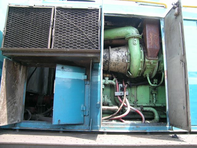
- Removable air filter screens leading to the clean air box in the left hand top side.
- The round green item is the turbocharger. The exhaust manifold is from the right of the turbo, the turbine is in the round body and the exhaust stack is the rusty looking pipe on the top. The clean air enters the turbo impeller from the top through the green pipe and is sent to the cylinders (or an inter cooler - not sure if this loco has one) through the cone on the left. The turbo shares an oil pressure pipe with the engine's (on the right) lubrication system.
- The two thick red cables are almost certainly the wires leading to the 24 Volts battery - an insulating block is used to keep the cables from swaying too much . You can almost see the starter motor solenoid (with the golden anodized label below the turbo cone). The corrugated sleeve could be carrying the pilot wires from the starting circuit.
- The item with flanges below the turbo cone could be the water pump and water pipes leading to it.
- The compressed air reservoir's rounded end can be seen on the left bottom.
- The cooling water pipe travels from left to right at the bottom.
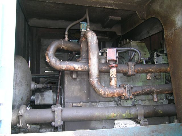
- The location of this picture is almost certainly at the junction of the long hood and the cab. The cab is located above the right top - the curved member would support the cab's floor.
- The cooling water pipe is being led to the radiator that is located in the short hood located beyond the cab.
- The engine's drive shaft is seen behind the air reservoir. The shaft leads into the hydraulic transmission which is the main item in the picture. The pipes leading into the the transmission carry the hydraulic fluid to the single motor located in between the axles.
- (Not seen in this pic) There is a lever in the gearbox with the motor that selects the top speed of the loco as 27 Kmph (high effort for shunting) or 65 Kmph (low effort for branch line operation and traveling distance).
- The blue and red item fitted on top of the hydraulic pipes may be for measurement of pressure or oil temperature.Maybe a pressure or temperature switch also.
- The hydraulic governor can be seen on top of the transmission - this has four control pipes leading to 16 possible power levels by controlling oil flow though the orifices - the throttle is connected to this device. The two flexible pipes leading out of the thick hydraulic pipes maybe for pressure gauges inside the cab - maybe a "before and after" type of gauge.
- The power shaft goes through the hydraulic transmission, under the cab floor to a right angle gear box and a clutch coupling to drive the radiator fan in the short hood.